
Remote sensing digital angle gauge

a digital angle gauge and remote sensing technology, applied in the direction of mechanical measuring arrangements, optical radiation measurement, instruments, etc., can solve the problems of large current angle measurement tools, inability to accurately measure the caster angle, and difficulty in measuring such angles, so as to achieve efficient input and receive instructions

Inactive Publication Date: 2010-03-23
SPX CORP
View PDF10 Cites 5 Cited by
  • Summary
  • Abstract
  • Description
  • Claims
  • Application Information

AI Technical Summary

Benefits of technology

"The present invention provides an apparatus and technique for measuring angles in confined spaces while still allowing the user to efficiently input instructions and receive the angle measurements without interference. The invention includes a sensor unit and an interface unit in communication with the sensor unit, which receives a signal from the sensor unit and determines the angle measurement based on the received signal and inputted data from the interface unit. The invention also includes a method of remotely sensing an angle by setting a zero point, receiving an offset value, and determining the angle measurement based on the data received from the sensor and the inputted offset value. The invention can be applied in various ways and can be utilized as a basis for designing other structures, methods, and systems for carrying out the several purposes of the invention."

Problems solved by technology

Measurement of such angles is also critical and difficult when being limited in confined spaces.
Current wheel alignment tools are not able to accurately measure the caster angle in a convenient, efficient and accurate manner.
Current angle measurement tools are large and the reading of measurements is difficult when measuring the angles due to low clearance or inaccessibility.
For example, current angle gauges will not fit in confined spaces where the rear casters of the vehicles are located.
Further, the current equipment is unable to include a remote display of the angle that is required when measuring in an inaccessible space, while displaying the measurement in a convenient and efficient manner.
However, even laser range finders cannot get an accurate measurement.
However, the confined space available for the measurement of the caster angle and the size of the current tools make it very difficult to measure the angles.
Thus the conventional tools cannot be used to measure angles, such as the caster angle of certain vehicles.

Method used


Image

  • Remote sensing digital angle gauge
  • Remote sensing digital angle gauge
  • Remote sensing digital angle gauge

Examples


Embodiment Construction

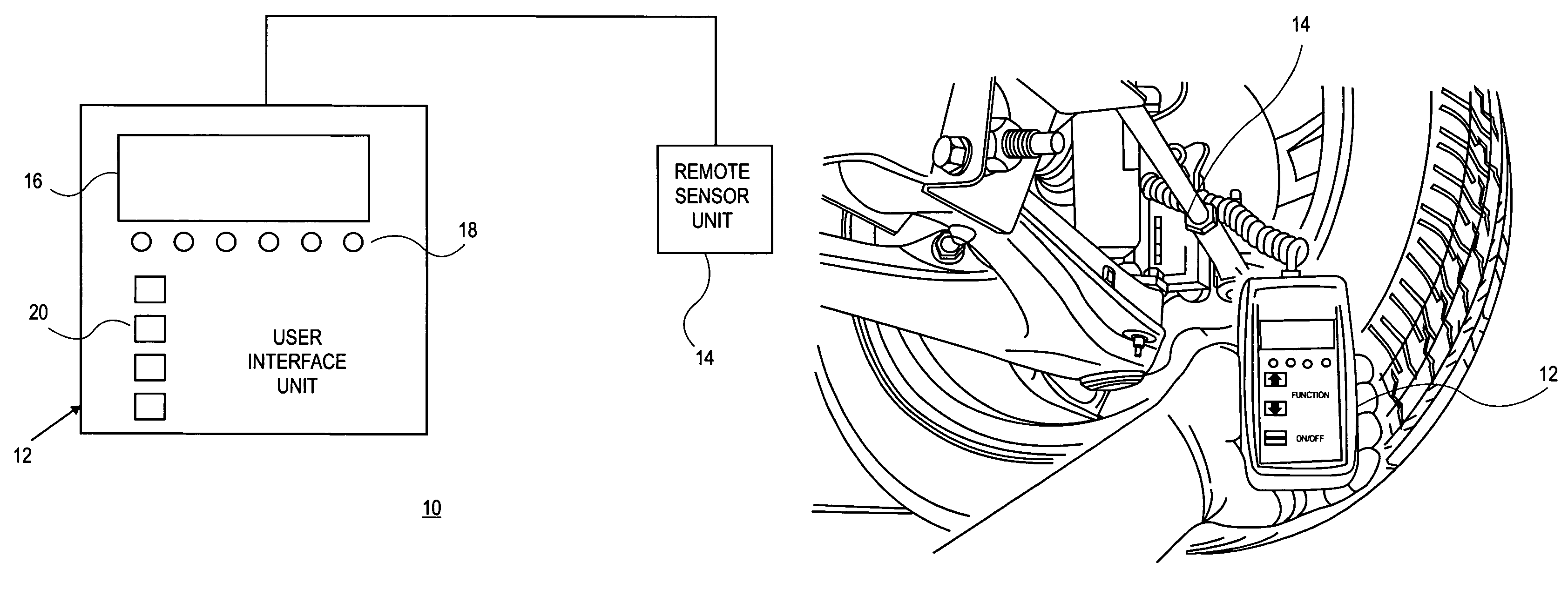
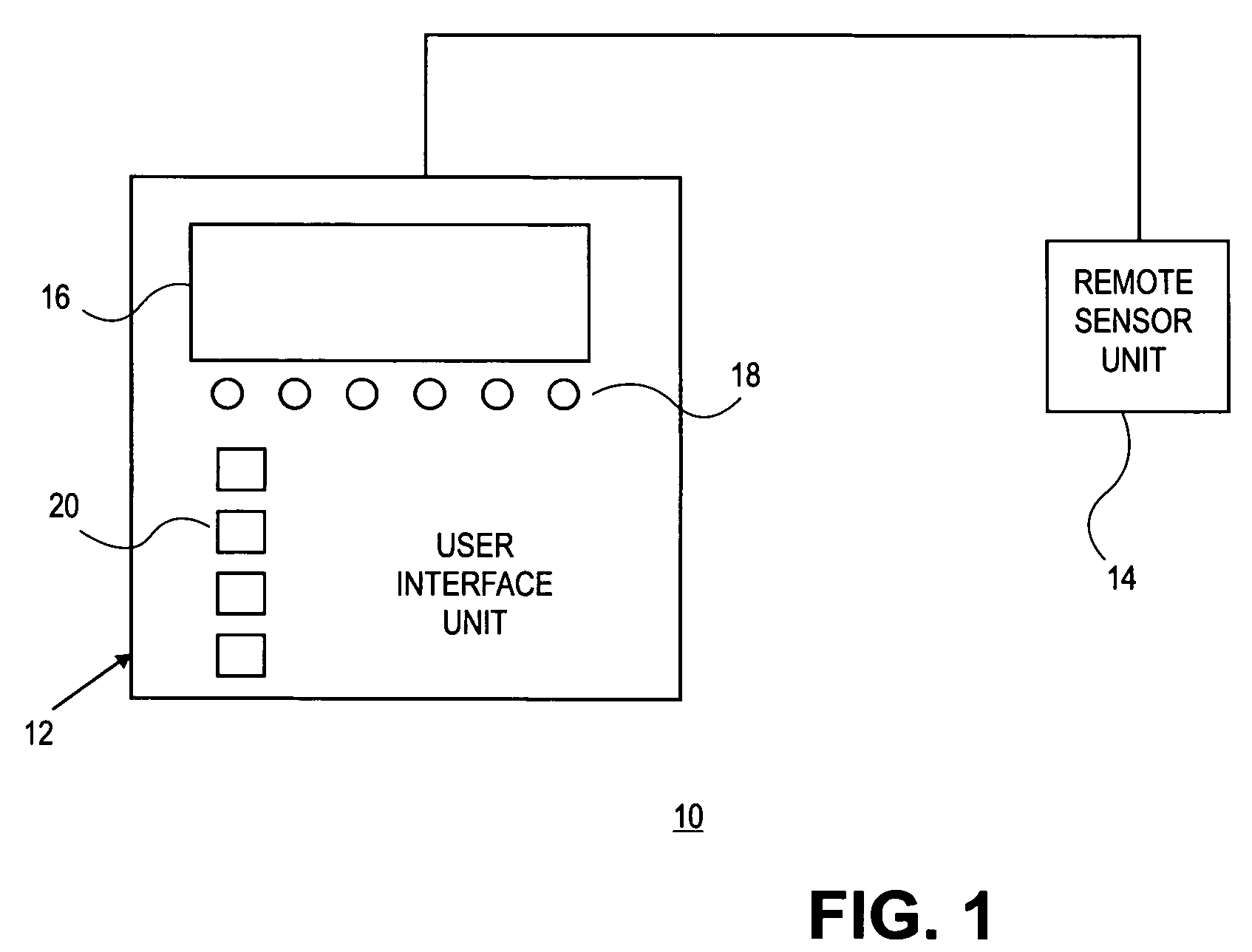
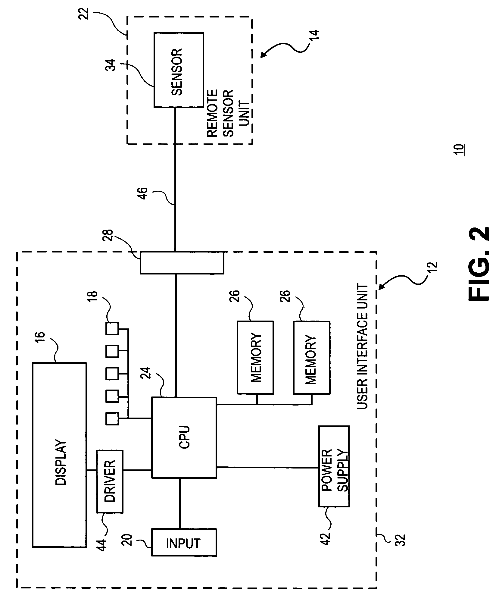
[0022]The invention will now be described with reference to the drawing figures, in which like reference numerals refer to like parts throughout. An embodiment in accordance with the present invention provides a remote sensing angle gauge, including a remote sensor for measuring an angle, and a user interface separate and remote from the sensor and in communication with the sensor. The user interface receives a signal from the resulting impulse of the sensor, and the user interface unit determines the angle measurement according to the received signal from the sensor and inputted data from the user interface. The present invention also provides a technique of remotely sensing an angle, including setting a zero point with respect to an area being measured, receiving an offset value from an input unit and storing the offset value in a memory, receiving through an input unit a selection of an orientation of the sensor, and determining the angle measurement according to the data receive...


PUM


Abstract

A remote sensing angle gauge includes a sensor responding to physical stimulus and transmitting a resulting impulse for measuring an angle, and a user interface separate and remote from said sensor and in communication with said sensor unit. The user interface receives a signal from the resulting impulse of said sensor unit, and determines the angle measurement according to the received signal from said sensor unit and inputted data from said interface unit. The inputted data by a user includes an offset and orientation of the sensor. The gauge can be zeroed before initiating the measurement. The sensor can be connected to the user interface through a detachable electrical connection. The sensor can include an adaptor accommodating a detachable and adjustable connection to an area being measured. The results of the measurement on the user interface can be remotely monitored, while measuring the angle with the sensor.

Description

FIELD OF THE INVENTION[0001]The present invention relates generally to a measurement apparatus and technique. More particularly, the present invention relates to an angle measurement apparatus and technique with a remote sensor.BACKGROUND OF THE INVENTION[0002]Accurate measurement of angles is important in a variety of fields including for example the manufacturing industries such as the automotive field. Measurement of such angles is also critical and difficult when being limited in confined spaces.[0003]For example, proper alignment of wheels of an automotive vehicle is important for both proper handling of the vehicle, as well as proper tire wear. One of the wheel alignment parameters, which is measured and adjusted in order to achieve proper wheel alignment, is the caster angle.[0004]Caster is an angle which the steering axis of a steerable wheel makes with respect to a vertical plane which is perpendicular to the longitudinal direction of the vehicles. The caster angle is consi...

Claims


Application Information

Patent Timeline
Patent Type & Authority Patents(United States)
IPC IPC(8): G01B11/26G01B5/00G01J1/00
CPCG01B21/26
Inventor WILLCOCK, KEVINSHEVELA, MICHAELBANAR, MICHAEL F.
Owner SPX CORP
Learn More