
Tool support apparatus

a technology of supporting apparatus and tools, which is applied in the direction of lifting devices, fishing, dwelling equipment, etc., can solve the problems of slow and inconvenient retrieval, difficulty for users, or other users to locate, or relocate, and existing handled tools used for agricultural, garden or yard maintenan

Inactive Publication Date: 2010-03-30
WESTGARDE WESLEY WADE
View PDF12 Cites 11 Cited by
  • Summary
  • Abstract
  • Description
  • Claims
  • Application Information

AI Technical Summary

Benefits of technology

"The present invention is a tool support apparatus that can be attached to the end of a tool handle. It includes a body that is secured to the handle and a ground piercing member that can be moved between an active position and a stored position. In the active position, the ground piercing member sticks out from the end of the handle, allowing it to be inserted into the ground to support the tool in an upright position. In the stored position, the ground piercing member is parallel to the handle so that it doesn't interfere with the tool's normal usage. The apparatus also includes means to lock the ground piercing member in a selected position."

Problems solved by technology

Existing handled tools that are used for the purpose of agricultural, gardening, or yard maintenance present a safety hazard when left laying down, or positioned horizontally on the ground, or site, because they may be stepped on, or driven on by support equipment (four wheelers, mowers, etc.).
Further, when these mentioned tools are left laying down, or positioned horizontally on a site or area surface they become difficult for the user, or other users to locate, or relocate, when desiring to utilize the tools, especially so if they are laying in tall grass or vegetation.
When two or more tools are used in conjunction with each other, as could be the case of using a rake and shovel, usually the shovel is stuck in the ground when using the rake, however the rake is usually dropped to the ground making it slow and inconvenient to retrieve.
Also tools that are left laying or positioned horizontally often collect soil, mud, or creatures such as slugs, and more so if the area or site is wet (rain or dew etc.), which may also decrease the working life of the tools.
Sometimes tools that are left laying on the ground or in grassy areas cannot be located, or are lost.
Existing handled tools that are used for the purpose of construction and more particularly asphalt tools similarly have the same inconveniences for locating, quick retrieval, safety issues, as well the tool becomes covered with hot sticky asphalt when left laying down, or positioned horizontally on a site or area surface.

Method used


Image

  • Tool support apparatus
  • Tool support apparatus
  • Tool support apparatus

Examples


Embodiment Construction

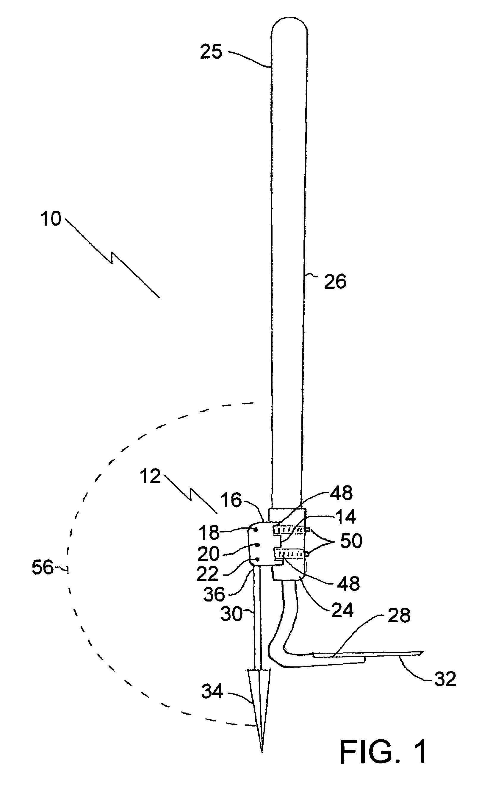
[0013]The tool support apparatus generally identified by reference numeral 10, will now be described with reference to FIG. 1 through FIG. 5.

Structure and Relationship of Parts

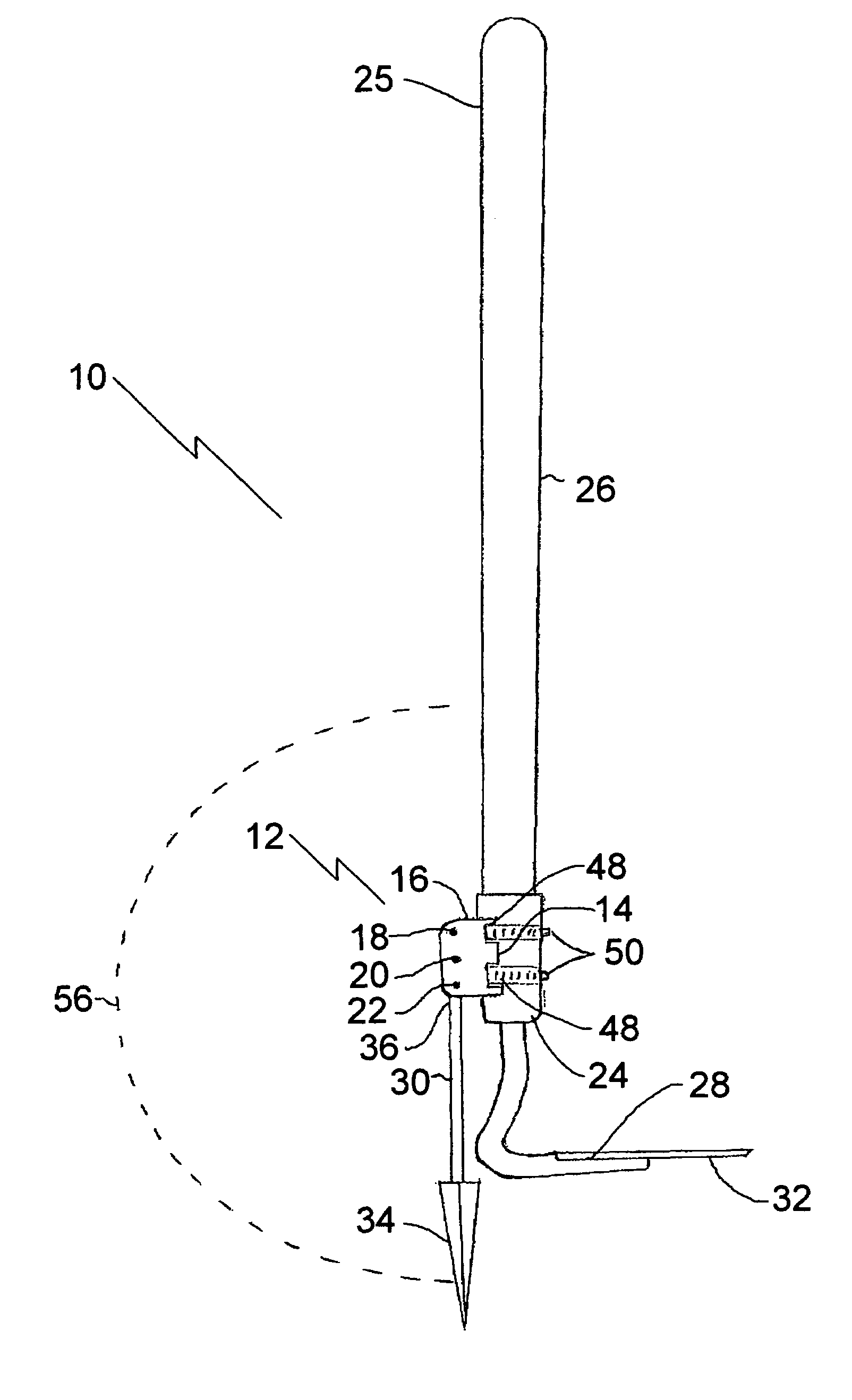
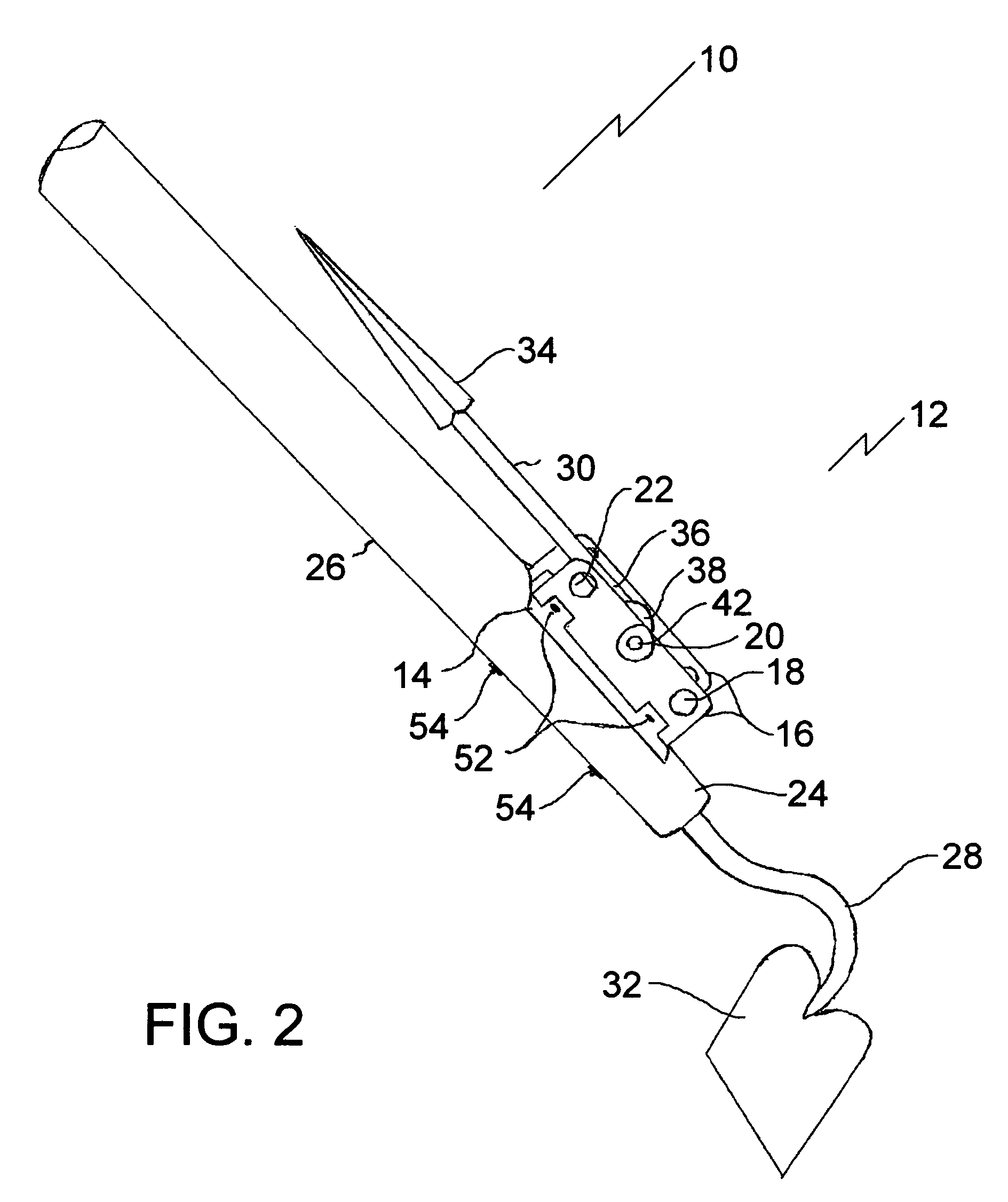
[0014]Referring to FIG. 3 and FIG. 4, tool support apparatus 10 has a body, generally indicated by reference numeral 12, which consists of a base 14 with two parallel walls 16. Parallel walls 16 have aligned pairs of holes 18, 20, 22. As will hereinafter be described, with reference to FIGS. 1, 2, and 5, body 12 is intended to be secured to an end 24 or 25 of a handle 26 of a tool 28, with attachment to end 24 being shown. There are various means for doing this, a few of which will be further described. Referring to FIG. 1 and FIG. 2, a ground piercing member 30 is pivotally secured to body 12 for pivotal movement between an operative position, illustrated in FIG. 1 and a stored position illustrated in FIG. 2. Referring to FIG. 1, in the operative position, ground piercing member 30 protrudes past end 24 or 25...


PUM


Abstract

A tool support apparatus includes a body adapted to be secured to an end of a handle of a tool. A ground piercing member is pivotally secured to the body for pivotal movement between an operative position and a stored position. In the operative position, the ground piercing member protrudes past the end of the handle, such that the ground piercing member can be inserted into the ground to support the handle of the tool in a substantially upright orientation. In the stored position, the ground piercing member is oriented substantially parallel to the handle so as not to interfere with the normal usage of the tool.

Description

CROSS-REFRENCE TO RELATED APPLICATION(S)[0001]This application claims priority from a U.S. Provisional Application, Ser. No. 60 / 685,393, entitled Garden tool attachment “spear-it”, filed May 31, 2005.FIELD OF THE INVENTION[0002]The present invention relates to a tool support apparatus applicable to, construction, agriculture, gardening or yard tools, such as, a weeder, claw, rake, hoe, edging knife, pick, or cultivator.BACKGROUND OF THE INVENTION[0003]Existing handled tools that are used for the purpose of agricultural, gardening, or yard maintenance present a safety hazard when left laying down, or positioned horizontally on the ground, or site, because they may be stepped on, or driven on by support equipment (four wheelers, mowers, etc.). These chances increase if the area or site has tall grass or vegetation. Further, when these mentioned tools are left laying down, or positioned horizontally on a site or area surface they become difficult for the user, or other users to locate,...

Claims


Application Information

Patent Timeline
Patent Type & Authority Patents(United States)
IPC IPC(8): A47G29/00F16M11/00
CPCA01B1/00A01B1/08A45F3/44
Inventor WESTGARDE, WESLEY WADE
Owner WESTGARDE WESLEY WADE
Learn More