Wedge based fastener

a fastener and edge technology, applied in the field of fasteners, can solve the problems of affecting the operation of the disk drive, and the procedure can take too much assembly time,

Active Publication Date: 2010-03-30
WESTERN DIGITAL TECH INC
View PDF64 Cites 68 Cited by
  • Summary
  • Abstract
  • Description
  • Claims
  • Application Information

AI Technical Summary

Benefits of technology

[0005]In one aspect, a fastener is provided that includes a shaft and a sleeve. The shaft extends along a longitudinal axis that passes through a cross-sectional centroid of the shaft. The sleeve is wrapped partially around the shaft. The sleeve comprises an inner surface adjacent the shaft, an outer surface, an upper extent, and a lower extent. The sleeve also comprises a first circumferential extent, a second circumferential extent, and a gap. The gap extends longitudinally from the upper extent to the lower extent and separates the first circumferential extent from the second circumferential extent. The sleeve has a first thickness adjacent the first circumferential extent and a second thickness between the second circumferential extent and the first circumferential extent. The first thickness is less than the second thickness. The sleeve has a first rotational position relative to the shaft and a second rotational position relative to the shaft different form the first rotational position. The longitudinal axis is in substantially the same location in both the first and second rotational positions.

Problems solved by technology

For example, screws take significant time to install because they generally require many revolutions to engage a first set of threads with a second set of threads.
In high-volume manufacturing, where assembly time should be minimized, this procedure can take too much assembly time, especially where several screws are used to connect the cover and base of a disk drive.
Also, coupling using mating metal screw threads is a process that can generate small metal particles that can interfere with the operation of the disk drive if such particles are introduced into the inside of the drive.

Method used


Image

  • Wedge based fastener
  • Wedge based fastener
  • Wedge based fastener

Examples


Embodiment Construction

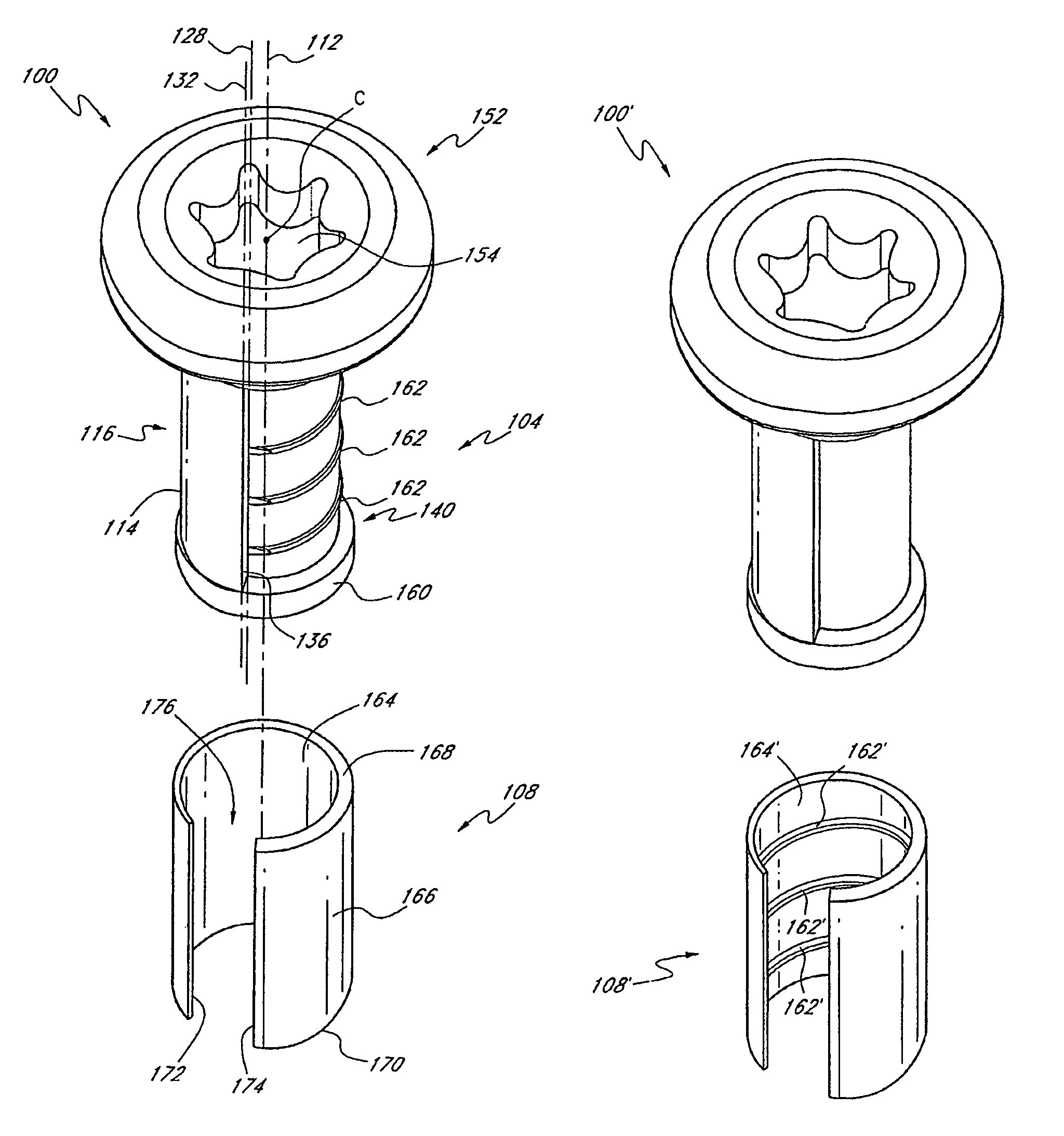
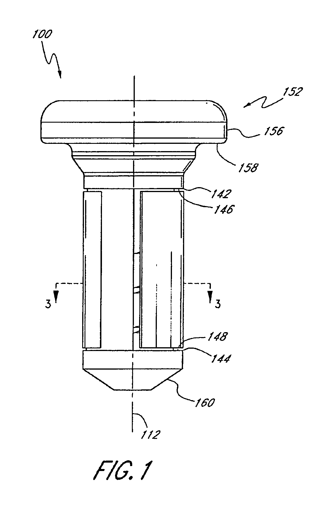
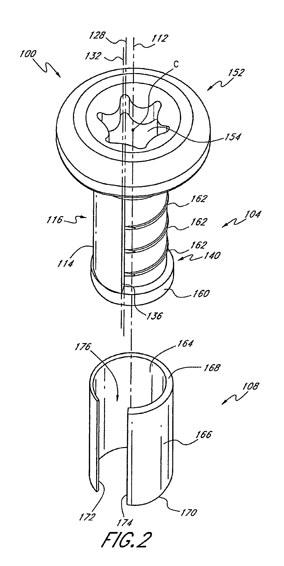
[0021]As discussed above, this application is directed to inventive fasteners. In various embodiments, the fasteners include one or more wedge-like members, which can be configured as a sleeve. These wedge-like members can be wrapped partially around a shaft of the fastener. Although the fasteners described herein are generally applicable, e.g., in environments where minimizing particle generation or assembly time is desirable, one non-limiting environment in which the fastener can be used is a disk drive. Another suitable environment is a computer or other user device in which the fasteners described herein can be used to secure components, such as a disk drive, to a rail, flange, or other mounting structure.

[0022]FIGS. 1-3 illustrate a first example embodiment of a fastener 100 that includes a shaft 104 and a sleeve 108. The shaft 104 and the sleeve 108 may be made of severable suitable materials. For example, the shaft 104 may be made of a metallic material, such as stainless ste...


PUM


Abstract

A fastener that includes a shaft and a sleeve is provided. The shaft extends along a longitudinal axis that passes through a central portion, e.g., the centroid of a head of the shaft. The sleeve is wrapped partially around the shaft. The sleeve has a gap that separates first and second circumferential extents thereof, a first thickness adjacent the first circumferential extent, and a second thickness between the second circumferential extent and the first circumferential extent. The first thickness is less than the second thickness. The sleeve has a first rotational position relative to the shaft and a second rotational position relative to the shaft different form the first rotational position. The longitudinal axis is in substantially the same location in both the first and second rotational positions.

Description

BACKGROUND OF THE INVENTION[0001]1. Field of the Invention[0002]This application relates to fasteners that can be used to couple structures together, which fasteners can include a sleeve wrapped partially around a shaft.[0003]2. Description of the Related Art[0004]A variety of fasteners have been used to couple two components together. For example, screws and adhesives have been used in disk drives to connect a cover to a base. Although screws can be used to connect a cover and a base of a disk drive together they have several disadvantages. For example, screws take significant time to install because they generally require many revolutions to engage a first set of threads with a second set of threads. Sufficient engagement of mating threads can require three or more revolutions of the screw. In high-volume manufacturing, where assembly time should be minimized, this procedure can take too much assembly time, especially where several screws are used to connect the cover and base of ...

Claims


Application Information

Patent Timeline
Patent Type & Authority Patents(United States)
IPC IPC(8): F16B33/00
CPCF16B2/14F16B2/18F16B19/00
Inventor LARSON, NILS E.LIEBMAN, MICHAEL K.GARBARINO, JONATHAN M.
Owner WESTERN DIGITAL TECH INC
Why Eureka
Try Eureka