
High-efficiency air intake for aerosol air samplers

a high-efficiency, air-intake technology, applied in the field of air sampling, to achieve the effect of small forward velocity

Inactive Publication Date: 2010-04-06
UNITED STATES OF AMERICA
View PDF1 Cites 19 Cited by
  • Summary
  • Abstract
  • Description
  • Claims
  • Application Information

AI Technical Summary

Benefits of technology

[0023]“Eduction” is defined herein as the tendency of a flow of gas or liquid to entrain molecules that are adjacent to the flow. The mechanism of eduction derives from the inherent molecular motions of liquids and gases; that is to say, when a jet of, say, air is blown into a volume of stationary air, the motions of the...

Problems solved by technology

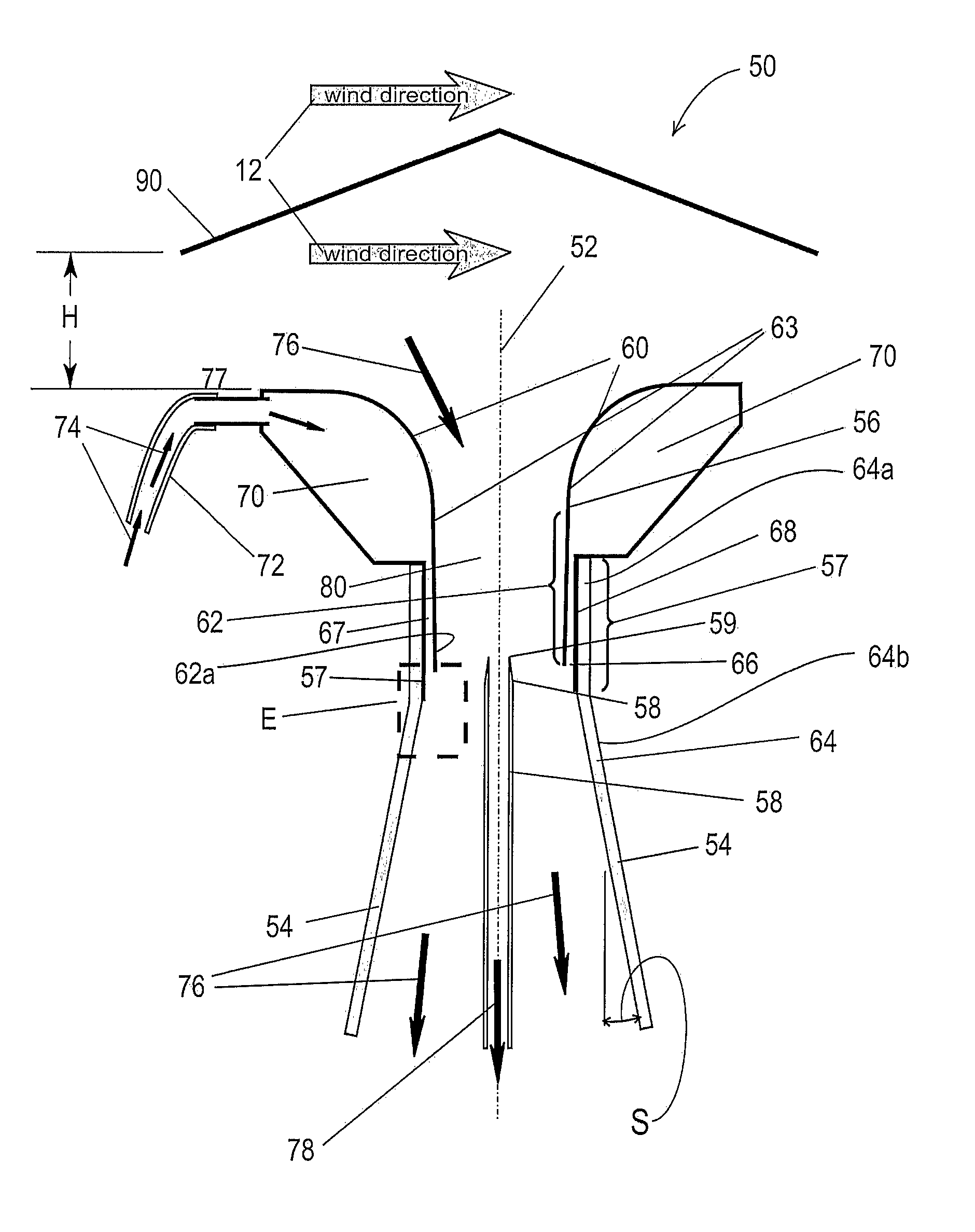
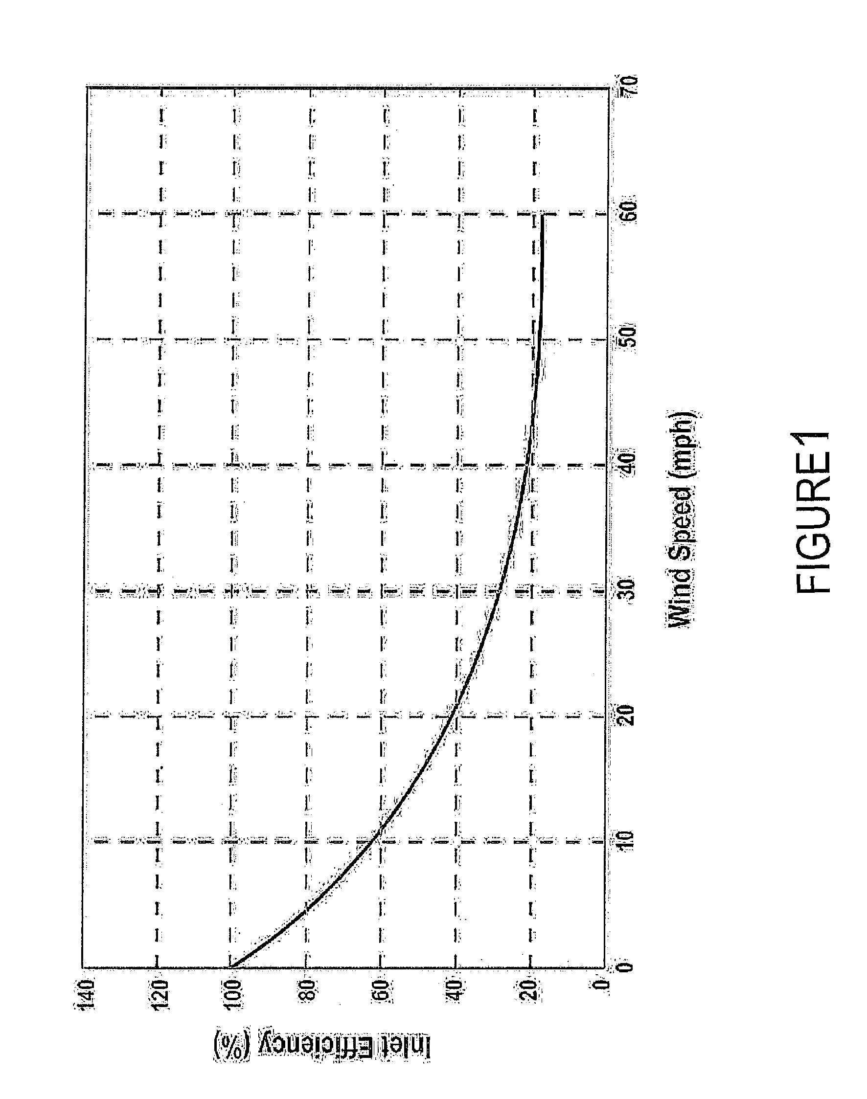
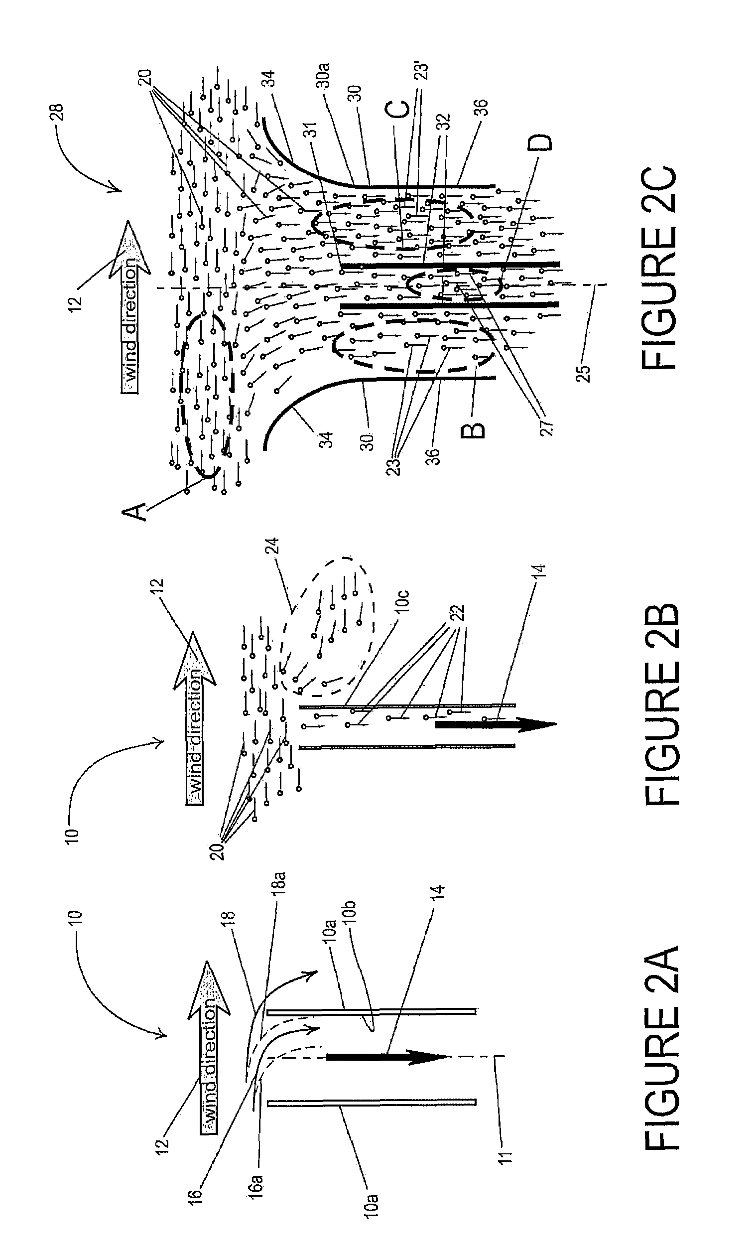
Aerosol air sampling often takes place in windy settings, wherein the sampled air has to be pulled from horizontal flow into a vertically oriented air intake.

Method used


Image

  • High-efficiency air intake for aerosol air samplers
  • High-efficiency air intake for aerosol air samplers
  • High-efficiency air intake for aerosol air samplers

Examples


second embodiment

[0073]FIG. 6 is a schematic cross sectional view of another embodiment of the present invention comprising an air intake portion 110 having a converging portion 111 and a circular cylindrical portion 112, the air intake portion 110 being essentially the same as the air intake 30 shown in FIG. 2C. A vertically oriented sampling tube 114 is disposed coaxially with the cylindrical portion 112 in such a way that the opening 115 to the sampling tube is located about one-quarter of the way into the lower part of the cylindrical portion 112. The air intake 110 of this second embodiment includes bend 117 of about 90 degrees, such that said bend 117 communicates with a more or less horizontally disposed tail portion 116 through which air, indicated by arrows 77 exhausts to the outside 120. Air moves within the sampling tube 114 in the direction indicated by the arrow 122. Contained within the tail portion is a fan or like pump 124 driven by a motor 126 housed therein.

embodiment 110

[0074]In net effect, the motor 126 and fan 124 exhaust air 77 and, in so doing, diverts, in a uniform way, a portion 77′ of the windy aerosol-containing air 128 into the air intake embodiment 110, such that an aerosol-laden quantity of air 122 is able to be drawn into the intake tube 114.


PUM


Abstract

The present invention relates to a method and apparatus for redirecting a flow of aerosol-containing air into, for example, an aerosol sampler. The apparatus comprising a device for redirecting a portion of the flow of aerosol-containing air into an air intake disposed within the flow of aerosol-containing air, preferably using eduction caused by a pressurized gas stream. A sampling tube having an opening for receiving aerosol-containing air is disposed within the air intake to collect the redirected portion of aerosol containing air.

Description

GOVERNMENT INTEREST[0001]The invention described herein may be manufactured, used and licensed by or for the United States Government.FIELD OF THE INVENTION[0002]The present invention relates to air sampling and, in particular, sampling of air that contains aerosol particles. More specifically, the present invention relates to the taking of aerosol-containing air samples in settings where sharp changes of airflow direction in the vicinity of the intake of the air sampler can adversely affect the acquisition of airborne aerosol particles.BACKGROUND OF THE INVENTION[0003]Aerosols consist of small particles, liquid or solid, that are suspended in air. Airborne dust particles, virus particles and bacteria can also comprise an aerosol.[0004]The study of aerosols has significance in many areas such as environmental and health studies, Homeland Security, and military defense, especially when the aerosol particles are pathogens. The device for collecting aerosol particles, commonly known as...

Claims


Application Information

Patent Timeline
IPC IPC(8): G01N1/00
CPCG01N1/2202G01N2001/2223
Inventor WISE, DANIEL G.
Owner UNITED STATES OF AMERICA
Learn More