Rudder pedal assembly including non-parallel slide rails

a technology of rudder pedal and slide rail, which is applied in the direction of mechanical control devices, instruments, vessel construction, etc., can solve the problems of large size and complexity of rudder pedal assemblies, and achieve the effect of small overall size and sufficient ergonomic feel for pilots

Inactive Publication Date: 2010-04-06
HONEYWELL INT INC
View PDF12 Cites 10 Cited by
  • Summary
  • Abstract
  • Description
  • Claims
  • Application Information

AI Technical Summary

Problems solved by technology

Although useful, safe, and robust, present rudder pedal assemblies are typically relatively large in size and complexity.

Method used


Image

  • Rudder pedal assembly including non-parallel slide rails
  • Rudder pedal assembly including non-parallel slide rails
  • Rudder pedal assembly including non-parallel slide rails

Examples


Embodiment Construction

[0022]The following detailed description is merely exemplary in nature and is not intended to limit the invention or the application and uses of the invention. Furthermore, there is no intention to be bound by any theory presented in the preceding background or the following detailed description.

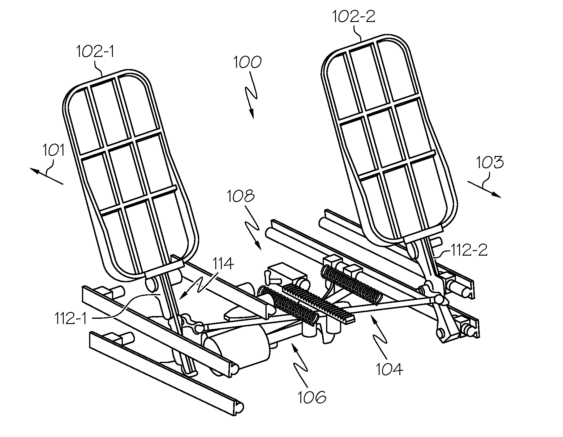
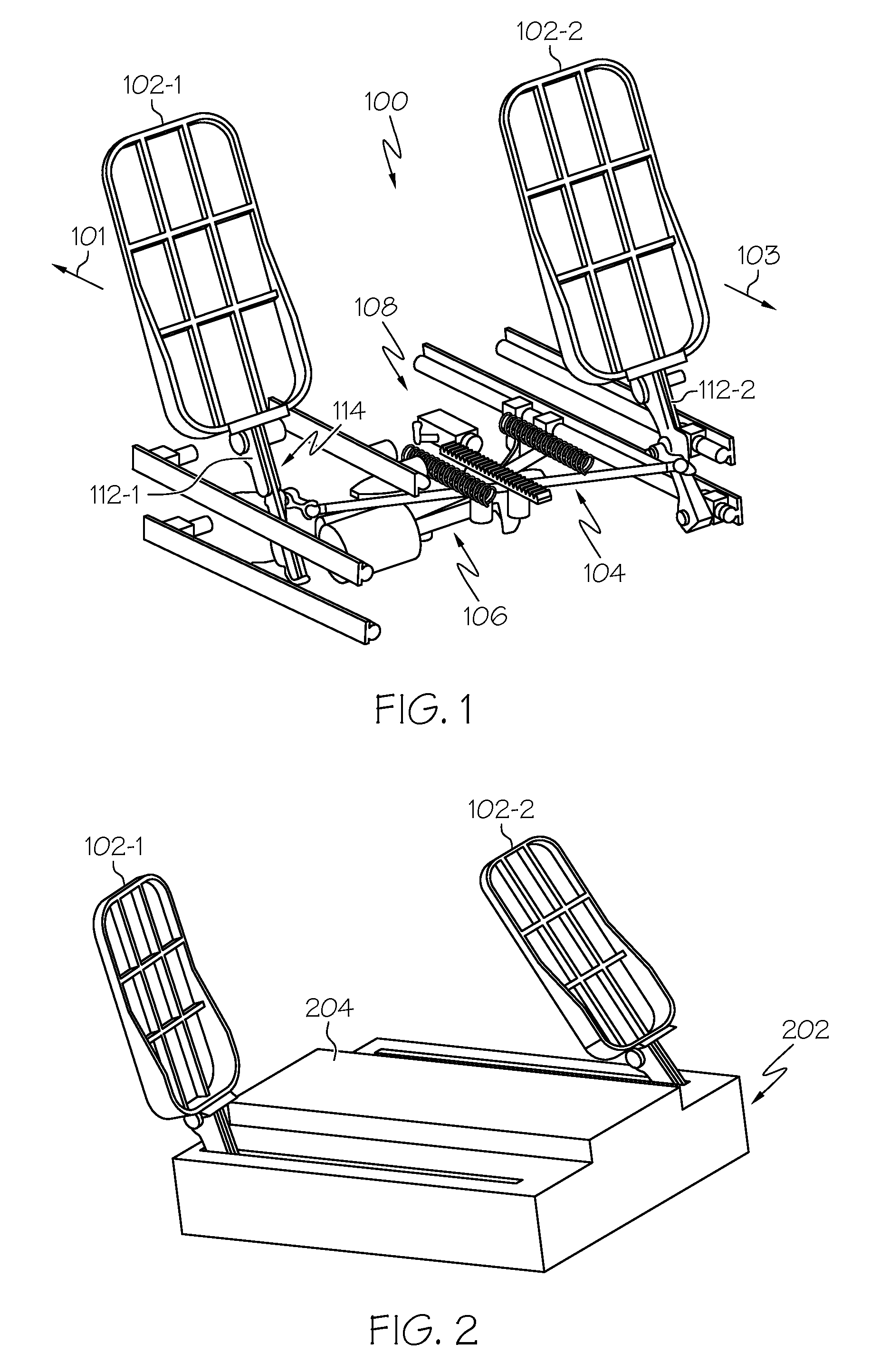
[0023]Turning now to FIG. 1, a plan view of an exemplary embodiment of an active rudder pedal system 100 is depicted, and includes a pair of rudder pedals 102 (102-1, 102-2), a force transfer mechanism 104, a rudder position command unit 106, and a position adjustment assembly 108. The system 100 is partially disposed within an enclosure 202, such as the one depicted in FIG. 2. Preferably, the rudder pedals 102 extend through a portion of the enclosure 202, which may be a cockpit floor board 204, and are configured to receive an input force from, for example, a pilot's foot and, in response to the received force, to move. Returning again to FIG. 1, it is seen that the rudder pedals 102 are e...


PUM


Abstract

A rudder pedal assembly exhibits sufficient ergonomic feel for a pilot, and is relatively small in overall size. The rudder pedal assembly includes a plurality of rails disposed non-parallel to each other within a common plane, and a rudder pedal. The rudder pedal is movably coupled to the plurality of rails and is configured to receive an input force in at least a first direction and a second direction. The rudder pedal is further configured, in response to the input force, to move along a path constrained by the plurality of rails in at least the first direction and the second direction, respectively, and within the common plane.

Description

CROSS-REFERENCES TO RELATED APPLICATIONS[0001]This application claims the benefit of U.S. Provisional Application No. 60 / 857,268, filed Nov. 6, 2006.TECHNICAL FIELD[0002]The present invention relates to a rudder pedal assembly and, more particularly, to rudder pedal assembly that includes non-parallel slide rails that provide improved ergonomic performance.BACKGROUND[0003]Aircraft typically include a plurality of flight control surfaces that, when controllably positioned, guide the movement of the aircraft from one destination to another. The number and type of flight control surfaces included in an aircraft may vary, but typically include both primary flight control surfaces and secondary flight control surfaces. The primary flight control surfaces are those that are used to control aircraft movement in the pitch, yaw, and roll axes, and the secondary flight control surfaces are those that are used to influence the lift or drag (or both) of the aircraft. Although some aircraft may ...

Claims


Application Information

Patent Timeline
Patent Type & Authority Patents(United States)
IPC IPC(8): B64C19/02
CPCB64C13/06B64C13/08G05G1/34G05G5/03G05G1/40G05G1/46G05G1/506G05G1/36B64C13/044
Inventor CHRISTENSEN, DONALD J.HANLON, CASEY
Owner HONEYWELL INT INC
Why Eureka
Try Eureka