MEMS switch with improved standoff voltage control

a technology of standoff voltage control and switch, which is applied in the direction of electrostatic/electro-adhesion relays, contacts, electrical apparatus, etc., can solve problems such as catastrophic failure of switch or downstream system

Active Publication Date: 2010-04-06
GENERAL ELECTRIC CO
View PDF1 Cites 43 Cited by
  • Summary
  • Abstract
  • Description
  • Claims
  • Application Information

AI Technical Summary

Problems solved by technology

In certain current switching applications, this self-actuation can result in catastrophic failure of the switch or downstream systems.

Method used


Image

  • MEMS switch with improved standoff voltage control
  • MEMS switch with improved standoff voltage control
  • MEMS switch with improved standoff voltage control

Examples


Embodiment Construction

[0018]In the following detailed description, numerous specific details are set forth in order to provide a thorough understanding of various embodiments of the present invention. However, those skilled in the art will understand that embodiments of the present invention may be practiced without these specific details, that the present invention is not limited to the depicted embodiments, and that the present invention may be practiced in a variety of alternative embodiments. In other instances, well known methods, procedures, and components have not been described in detail.

[0019]Furthermore, various operations may be described as multiple discrete steps performed in a manner that is helpful for understanding embodiments of the present invention. However, the order of description should not be construed as to imply that these operations need be performed in the order they are presented, nor that they are even order dependent. Moreover, repeated usage of the phrase “in one embodiment...


PUM


Abstract

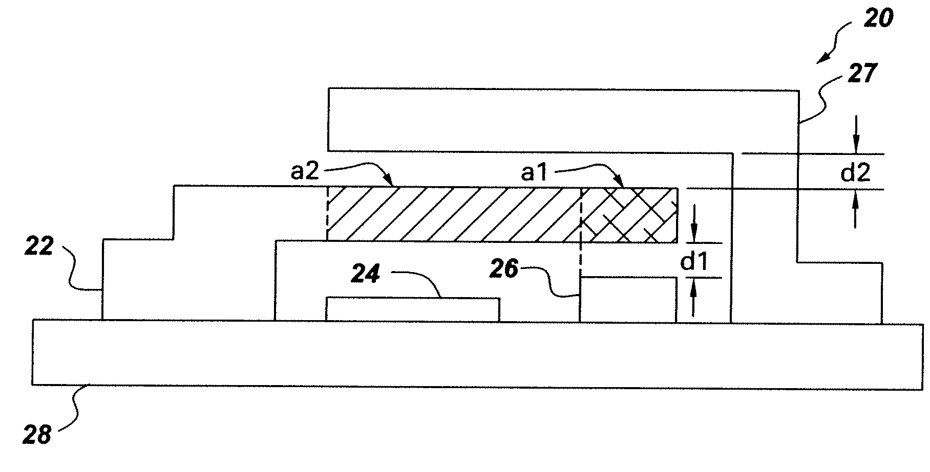
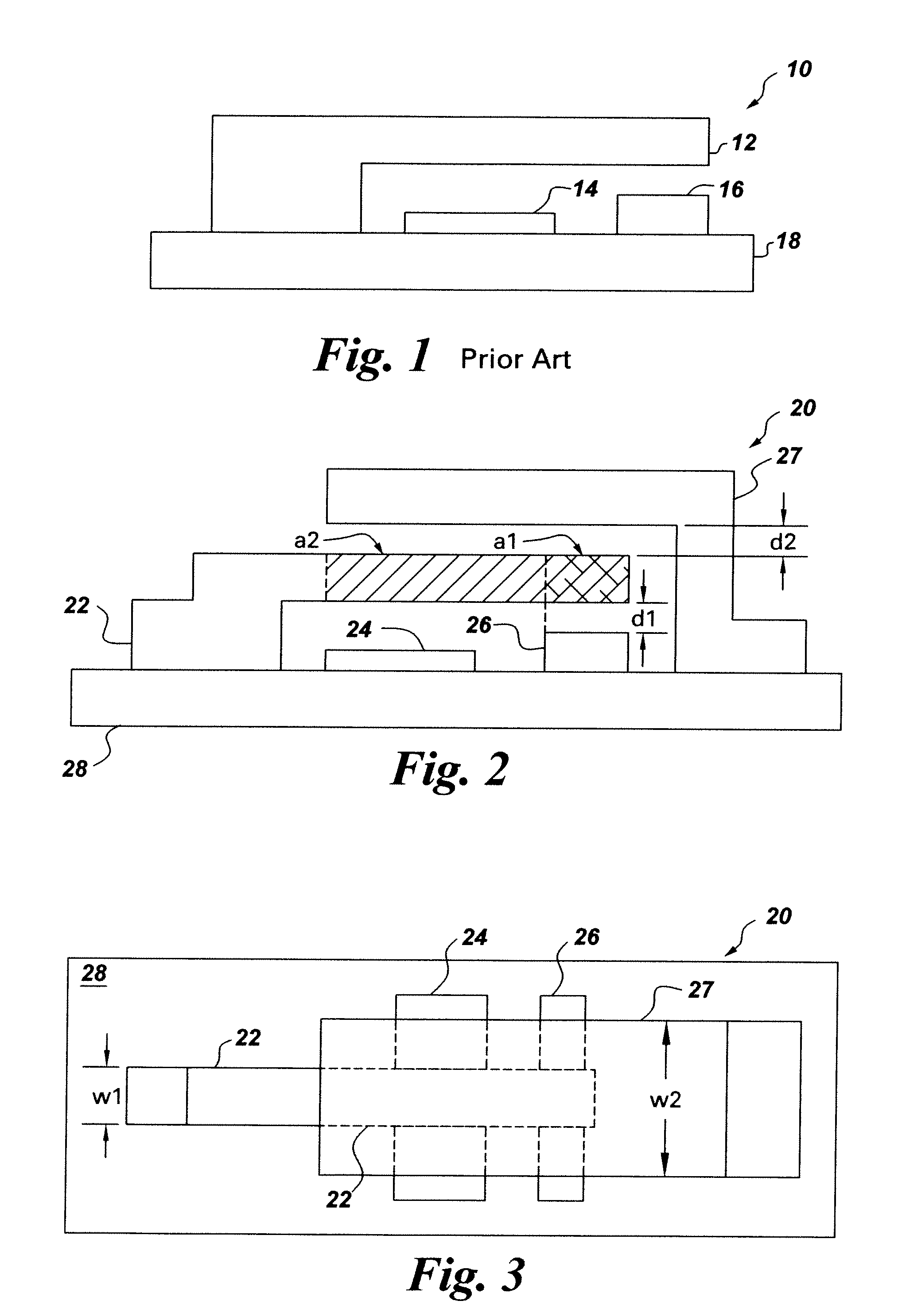
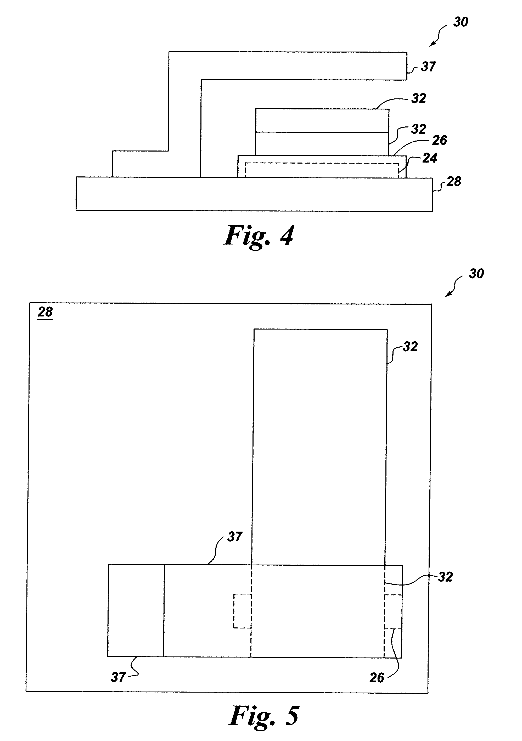
A MEMS switch is provided including a substrate, a movable actuator coupled to the substrate and having a first side and a second side, a first fixed electrode coupled to the substrate and positioned on the first side of the movable actuator to generate a first actuation force to pull the movable actuator toward a conduction state, and a second fixed electrode coupled to the substrate and positioned on the second side of the movable actuator to generate a second actuation force to pull the movable actuator toward a non-conducting state.

Description

BACKGROUND[0001]Embodiments of the invention relate generally to a micro-electromechanical system (MEMS) switch.[0002]Microelectromechanical systems (MEMS) generally refer to micron-scale structures that can integrate a multiplicity of functionally distinct elements such as mechanical elements, electromechanical elements, sensors, actuators, and electronics, on a common substrate through micro-fabrication technology. MEMS generally range in size from a micrometer to a millimeter in a miniature sealed package. A MEMS switch has a movable actuator that is moved toward a stationary electrical contact by the influence of a gate or electrode positioned on a substrate.[0003]FIG. 1 illustrates a conventional MEMS switch in an open or non-conducting state according to the prior art. The MEMS switch 10 includes a substrate 18, a movable actuator 12, a contact 16 and control electrode 14 mechanically coupled to the substrate 18. In operation, the movable actuator 12 is moved toward the contac...

Claims


Application Information

Patent Timeline
Patent Type & Authority Patents(United States)
IPC IPC(8): H01P1/10H01H57/00
CPCH01H59/0009H01H1/0036B81B7/02B81B7/00H01H59/00
Inventor PREMERLANI, WILLIAM JAMESKEIMEL, CHRISTOPHER FREDSUBRAMANIAN, KANAKASABAPATHIWANG, XUEFENGAIMI, MARCO FRANCESCO
Owner GENERAL ELECTRIC CO
Why Eureka
Try Eureka