Methods for modeling, displaying, designing, and optimizing fixed cutter bits

a technology of fixed cutter bits and design methods, applied in the field of fixed cutter drill bits, can solve the problems of inability to achieve the most accurate reflection of drilling, significant expense involved in the design and manufacture of drill bits and in the drilling of well bores, and inaccurate prediction of the response of an actual bit drilling in earth formation

Active Publication Date: 2010-04-06
SMITH INT INC
View PDF70 Cites 67 Cited by
  • Summary
  • Abstract
  • Description
  • Claims
  • Application Information

AI Technical Summary

Problems solved by technology

Significant expense is involved in the design and manufacture of drill bits and in the drilling of well bores.
While these models have been useful in that they provide a means for analyzing the forces acting on the bit, using them may not result in a most accurate reflection of drilling because these models rely on generalized theoretical approximations (typically some equations) of cutter and formation interaction that may not be a good representation of the actual interaction between a particular cutting element and the particular formation to be drilled.
Assuming that the same general relationship can be applied to all cutters and all earth formations, even though the constants in the relationship are adjusted, may result the inaccurate prediction of the response of an actual bit drilling in earth formation.

Method used


Image

  • Methods for modeling, displaying, designing, and optimizing fixed cutter bits
  • Methods for modeling, displaying, designing, and optimizing fixed cutter bits
  • Methods for modeling, displaying, designing, and optimizing fixed cutter bits

Examples


Embodiment Construction

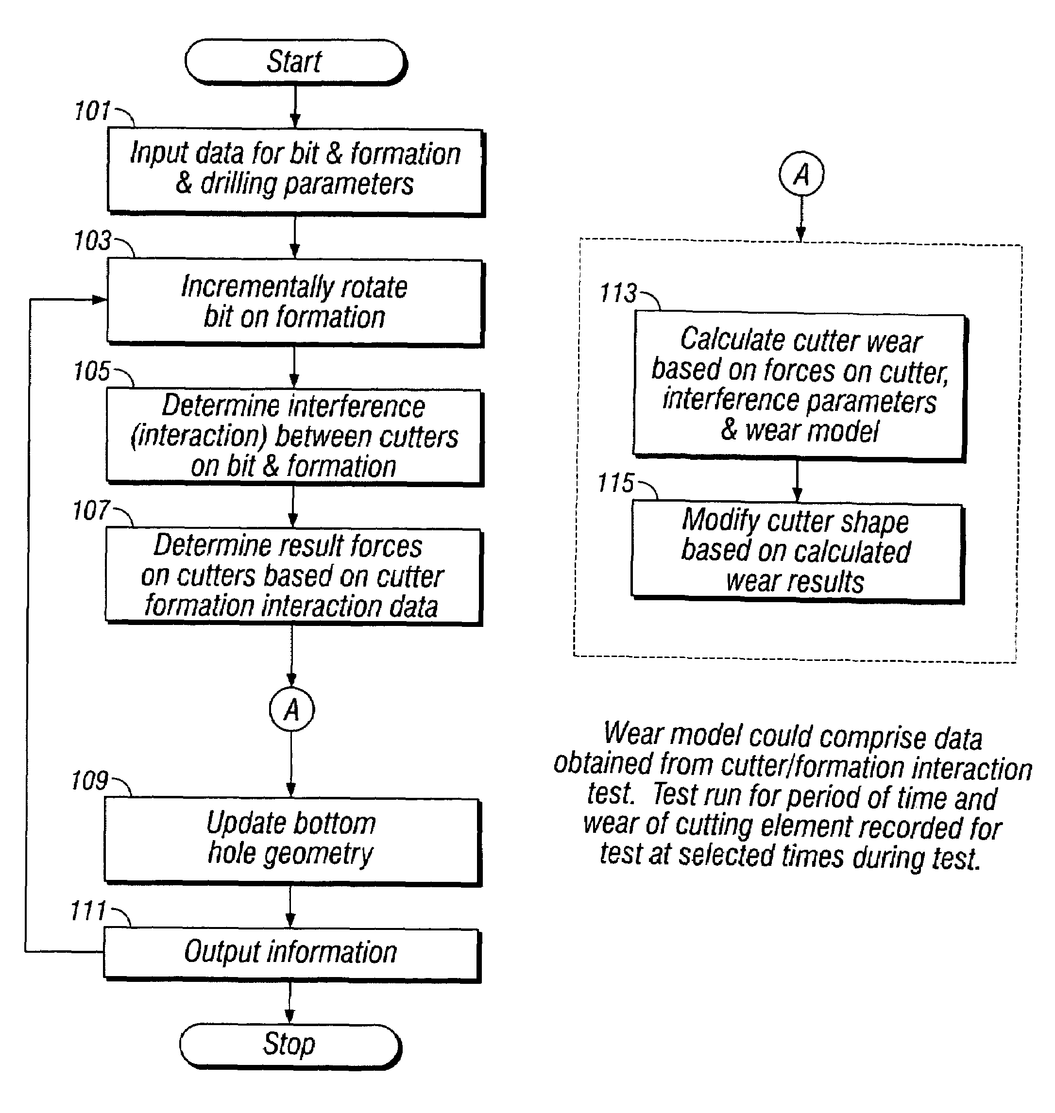
[0055]The present invention provides methods for modeling the performance of fixed cutter bits drilling earth formations. In one aspect, a method takes into account actual interactions between cutters and earth formations during drilling. Methods in accordance with one or more embodiments of the invention may be used to design fixed cutter drill bits, to optimize the performance of bits, to optimize the response of an entire drill string during drilling, or to generate visual displays of drilling.

[0056]In accordance with one aspect of the present invention, one or more embodiments of a method for modeling the dynamic performance of a fixed cutter bit drilling earth formations includes selecting a drill bit design and an earth formation to be represented as drilled, wherein a geometric model of the bit and a geometric model of the earth formation to be represented as drilled are generated. The method also includes incrementally rotating the bit on the formation and calculating the in...


PUM


Abstract

In one aspect, the invention provides a method for modeling the performance of a fixed cutter bit drilling an earth formation. In one embodiment, the method includes selecting a drill bit and an earth formation to be represented as drilled, simulating the bit drilling the earth formation, displaying the simulating, and adjusting at least one parameter affecting the performance. The method of design is used to make a fixed cutter drill bit. In another embodiment the method includes numerically rotating the bit, calculating bit interaction with the earth formation during the rotating, and determining the forces on the cutters during the rotation based on the calculated interaction with earth formation and empirical data.

Description

CROSS-REFERENCE TO RELATED APPLICATIONS[0001]This application claims priority, pursuant to 35 U.S.C. §119(e), to U.S. Provisional Patent Application Ser. No. 60 / 485,642, filed Jul. 9, 2003. This application claims the benefit, pursuant to 35 U.S.C. §120, of U.S. patent application Ser. No. 09 / 635,116, filed Aug. 9, 2000 and U.S. patent application Ser. No. 09 / 524,088, now U.S. Pat. No. 6,516,293, filed Mar. 13, 2000. All of these applications are expressly incorporated by reference in their entirety.[0002]Further, U.S. patent application Ser. No. 10 / 888,523 entitled “Methods For Designing Fixed Cutter Bits and Bits Made Using Such Methods” filed on Jul. 9, 2004, U.S. patent application Ser. No. 10 / 888,354 entitled “Methods for Modeling Wear of Fixed Cutter Bits and for Designing and Optimizing Fixed Cutter Bits,” filed on Jul. 9, 2004, and U.S. patent application Ser. No. 10 / 888,446 entitled “Methods For Modeling, Designing, and Optimizing Drilling Tool Assemblies,” are expressly in...

Claims


Application Information

Patent Timeline
Patent Type & Authority Patents(United States)
IPC IPC(8): G06G7/48E21B12/02E21B7/00E21B10/00
CPCE21B10/00
Inventor HUANG, SUJIAN J.CARIVEAU, PETER THOMAS
Owner SMITH INT INC
Why Eureka
Try Eureka