Plug connector

a technology of plug and socket, applied in the direction of coupling device connection, coupling protective earth/shielding arrangement, electric discharge lamps, etc., can solve the problems of unstably alternated impedance of usb 3.0 connector, 480 mbps transmission speed, and usb 2.0 transmission protocol not meeting the current transmission speed requirement of these electronic devices, etc., to achieve the effect of convenient connection of soldering terminals

Active Publication Date: 2010-04-13
ADVANCED CONNECTEK INC
View PDF8 Cites 85 Cited by
  • Summary
  • Abstract
  • Description
  • Claims
  • Application Information

AI Technical Summary

Benefits of technology

[0008]The main objective of the invention is to provide a plug connector capable o

Problems solved by technology

However, the USB 2.0 transmission protocol only allows a maximum transmission speed of 480 Mbps.
Because electronic devices are constantly developed to increase transmission speed, the USB 2.0 transmission protocol does not meet the current transmission speed requirement of these electronic devices.
Transmitting high frequency signals usually encounters electromagnetic interference from nearby electronic components so that the impedance of USB 3.0 connector unstably alternates

Method used


Image

  • Plug connector
  • Plug connector
  • Plug connector

Examples


Embodiment Construction

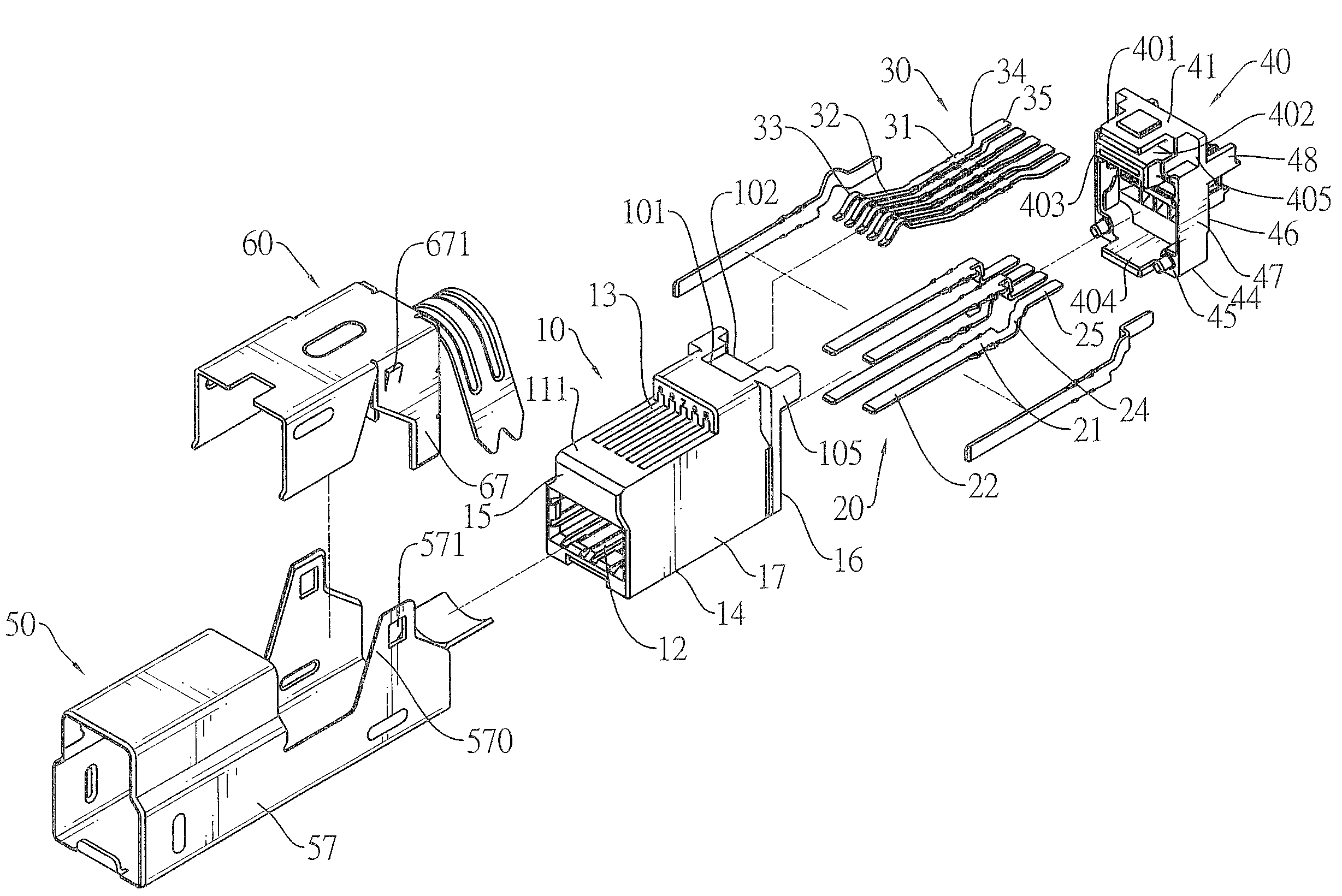
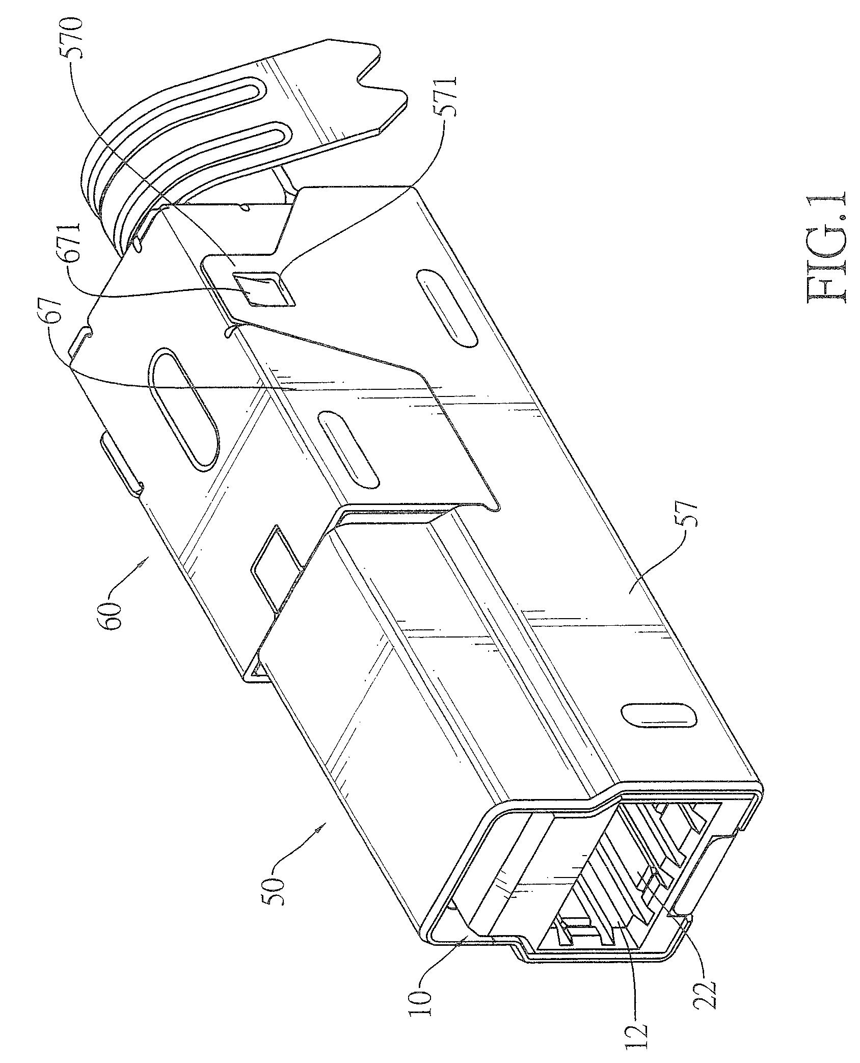
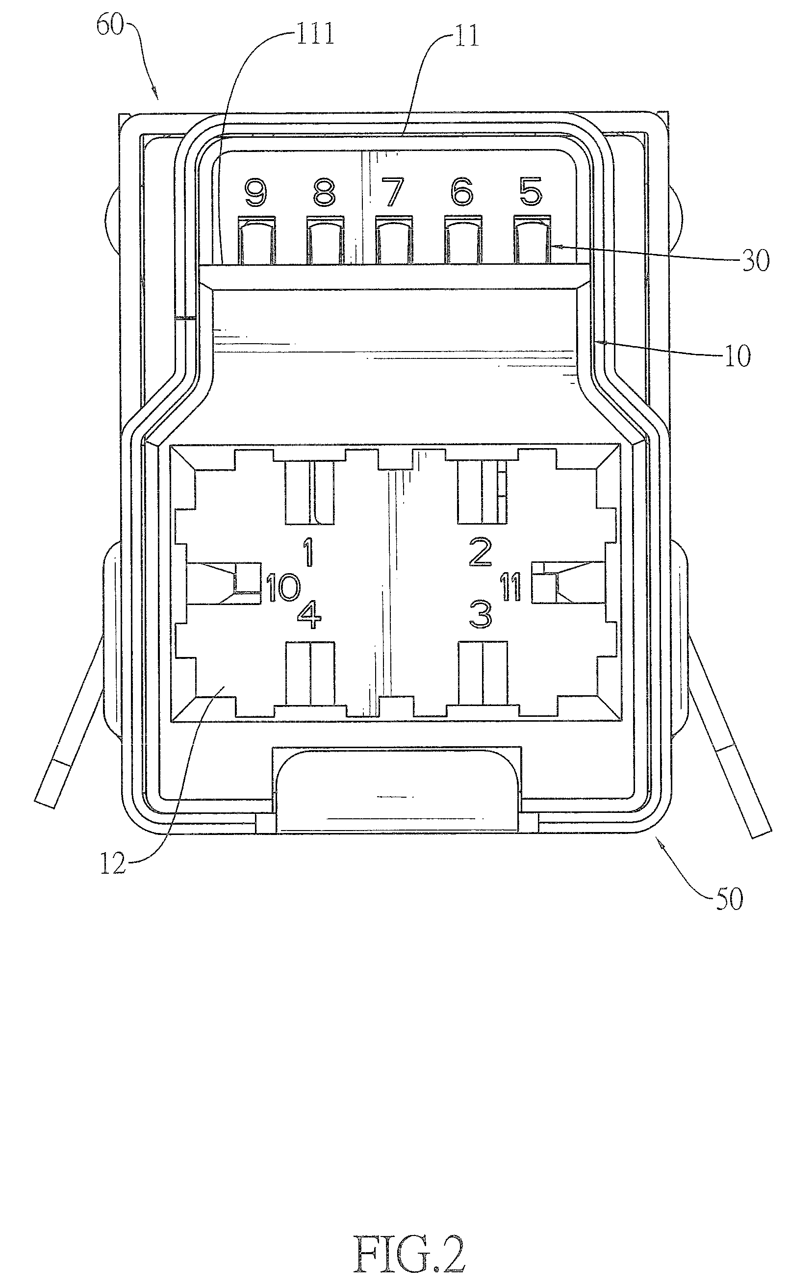
[0023]With reference to FIGS. 1 to 4, a plug connector in accordance with the present invention may comply with the Universal Serial Bus (USB) 3.0 and 2.0 transmission protocols and comprises an insulative housing (10), a plurality of first terminals (20), a plurality of second terminals (30), a positioning bracket (40) and a metal shell assembly.

[0024]With further reference to FIGS. 7 to 10, the insulative housing (10) has a top (11), a bottom (14), a front (15), a rear (16) and two opposite sides (17) and may further have a plurality of first mounting holes (100a), a recessed portion (111), a plurality of mounting grooves (13), a plurality of second mounting holes (100b), a first socket hole (12) and a lumpy engaging portion.

[0025]The first mounting holes (100a) are defined in the rear (16).

[0026]The recessed portion (111) is defined on the top (11) adjacent to the front (15).

[0027]The mounting grooves (13) are defined in the recessed portion (111).

[0028]The second mounting holes ...


PUM


Abstract

A plug connector has an insulative housing, a plurality of first terminals, a plurality of second terminals and a positioning bracket. The terminals are mounted in the insulative housing and each terminal has a soldering portion. The positioning bracket is mounted on the insulative housing and has a positioning protrusion having a top surface and a bottom surface respectively holding the soldering portions on two levels. The soldering portions are arranged in two levels to facilitate soldering wires to the soldering portions.

Description

BACKGROUND OF THE INVENTION[0001]1. Field of the Invention[0002]The present invention relates to a connector, and more particularly to a plug connector capable of transmitting high frequency signals and facilitates soldering terminals thereof.[0003]2. Description of Related Art[0004]Conventional Universal Serial Bus (USB) 2.0 connectors are popular in various electronic devices. However, the USB 2.0 transmission protocol only allows a maximum transmission speed of 480 Mbps. Because electronic devices are constantly developed to increase transmission speed, the USB 2.0 transmission protocol does not meet the current transmission speed requirement of these electronic devices. Therefore, the USB Implementers Forum (USB IF) is setting up a USB 3.0 transmission protocol that may achieve a theoretical maximum transmission speed of 4.8 Gbps, almost 10 times of that of the USB 2.0 transmission protocol.[0005]However, to implement the transmission of 4.8 Gbps, terminals of a USB 3.0 connecto...

Claims


Application Information

Patent Timeline
IPC IPC(8): H01R13/648
CPCH01R24/60H01R13/65802H01R13/506H01R2107/00H01R13/6582H01R13/658
Inventor WANG, FANG-HONGDUAN, SHU-LINCHEN, CHING-TIENHOU, PIN-YUANKO, WEN-CHIH
Owner ADVANCED CONNECTEK INC
Why Eureka
Try Eureka