Three-way stopcock, and liquid transfusion circuit or blood transfusion circuit either using the three-way stopcock

a stopcock and liquid transfusion technology, applied in mechanical equipment, infusion syringes, transportation and packaging, etc., can solve the problems of difficult to precisely administer medical fluid, bacteria entering, and inability to close all flow passages

Inactive Publication Date: 2010-04-13
JMS CO LTD
View PDF31 Cites 80 Cited by
  • Summary
  • Abstract
  • Description
  • Claims
  • Application Information

AI Technical Summary

Benefits of technology

[0012]In view of the above-stated circumstances, an object of the present invention is to provide a three-way stopcock that can reduce a stagnated portion of a fluid in a fluid flow passage and can be opened / closed in the same manner as the conventional operation methods.
[0014]With this configuration, the three flow passage openings are provided so as to be open to the flow passage switching portion, and the two fluid flow passages connecting the respective flow passage openings are formed to be capable of communicating with each other. Therefore, the flow of a fluid can reach a space in the branch opening also, and by performing the priming or the like, a stagnated portion of the fluid can be eliminated.
[0016]In addition, in the three-way stopcock according to the present invention, it is preferable that the third flow passage opening is formed with two flow passage openings, one of which communicates with the first flow passage opening and the other of which communicates with the second flow passage opening, and at a side wall portion where the two flow passage openings are formed in the third flow passage opening, a groove portion is provided so as to allow communication between the two fluid flow passages. Even in the case where a space is not formed in the branch opening due to a difference in the type of the injection port, a stagnated portion of the fluid can be eliminated by conducting the priming or the like.
[0017]In addition, in the three-way stopcock according to the present invention, it is preferable that the two flow passage openings in the third flow passage opening are provided to be arranged in a vertical direction of the body. This configuration can reduce the degree of the shift in an angular position when making the portions of the flow passage switching portion having none of the three flow passage openings face the respective branch openings of the body.
[0018]In addition, in the three-way stopcock according to the present invention, it is preferable that an injection port is provided at a side wall portion that forms the third branch opening. Furthermore, it is preferable that the injection port is capable of being inserted with an insertion member having a blunt tip and is capable of maintaining liquid-tightness.

Problems solved by technology

The third branch pipe 33, however, might be opened to the outside during the mixture injection, resulting in the possibility that bacteria get into there.
Due to the presence of the stagnated portion, a medical fluid to be given might remain there, which causes a problem that it becomes difficult to administer the medical fluid precisely.
These three-way stopcocks, however, have a drawback in that a closing of all of the flow passages cannot be made by adopting a method in which an angular position of the fluid flow passage is shifted slightly, which is a normal method in the conventional three-way stopcocks.
In the practical medical scenes, in particular, complicated operations should be done securely in a short time, and therefore the three-way stopcock having such a configuration has the possibility of operating errors occurring during the use thereof.

Method used


Image

  • Three-way stopcock, and liquid transfusion circuit or blood transfusion circuit either using the three-way stopcock
  • Three-way stopcock, and liquid transfusion circuit or blood transfusion circuit either using the three-way stopcock
  • Three-way stopcock, and liquid transfusion circuit or blood transfusion circuit either using the three-way stopcock

Examples


Embodiment Construction

[0033]The following describes a three-way stopcock according to embodiments of the present invention in detail, with reference to the attached drawings.

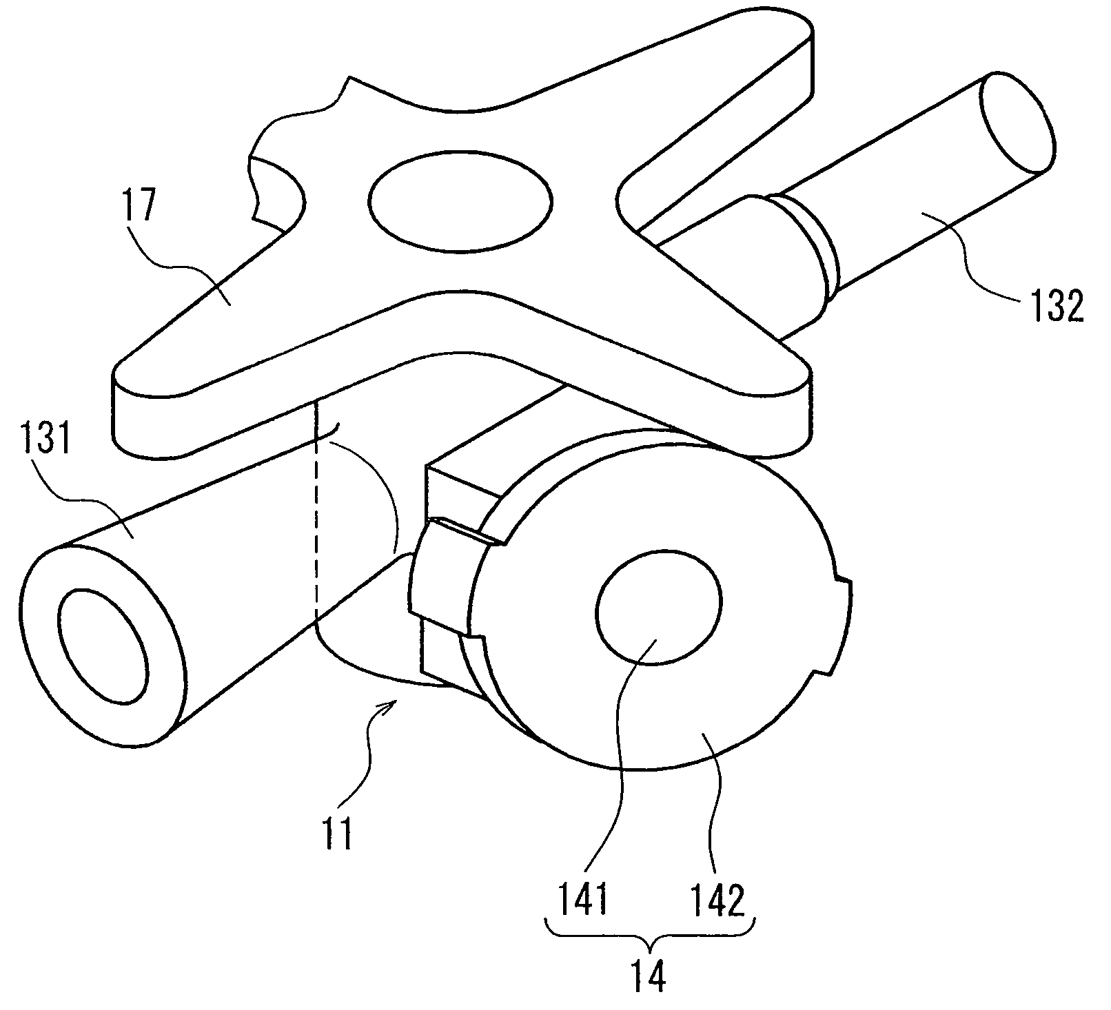
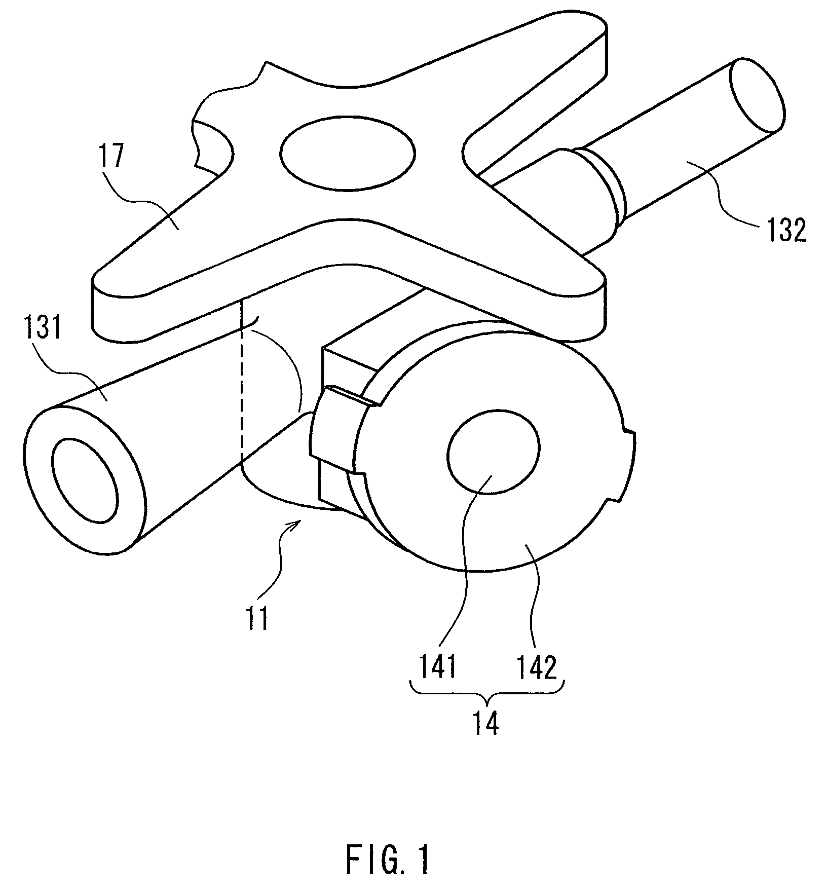
[0034]First, FIG. 1 is a perspective view of a three-way stopcock according to an embodiment of the present invention. The three-way stopcock according to the embodiment of the present invention is configured with a substantially cylindrical-shaped body 11 having three branch openings on the periphery thereof and a flow passage switching portion. The flow passage switching portion is mounted so as to be rotatable relative to the body 11 and provide fluid-tightness, has three flow passage openings that form a fluid flow passage so as to allow the communication between predetermined branch openings out of the respective branch openings of the body 11 and is configured integrally with a handle 17.

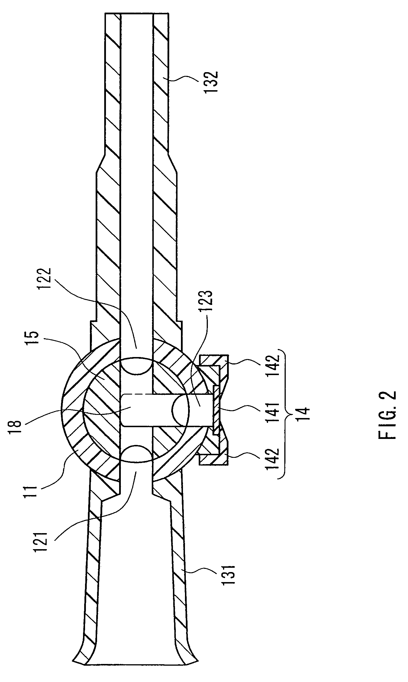
[0035]FIG. 2 is a transverse sectional view of the three-way stopcock according to the embodiment of the present invention. As shown in FIG. 2...


PUM


Abstract

A three-way stopcock that can be opened / closed in the same manner as conventional operation methods and can reduce stagnated portions of fluid in a fluid flow passage. Out of branch openings, a first branch opening and a second branch opening are arranged on a straight line, and a third branch opening is directed perpendicularly to the line connecting the first and second branch openings. Provided at a flow passage switch portion are a first flow-passage opening and a second flow-passage opening that are arranged on a straight line and a third flow-passage opening that is directed perpendicularly to the line connecting the first and second bran openings.

Description

TECHNICAL FIELD[0001]The present invention relates to a three-way stopcock capable of changing the route of a fluid flow passage by performing a rotational operation of a flow passage switching portion provided in a body having three branch openings so as to allow the communication between predetermined branch openings out of the three branch openings, and relates to a liquid transfusion tubing set or a blood transfusion tubing set using the same.BACKGROUND ART[0002]When a medical treatment is conducted by liquid transfusion or blood transfusion in medical facilities, a three-way stopcock is used for carrying out mixture injection of different types of medical fluid and for taking a fluid flowing through a fluid flow passage. FIG. 9 shows an overall perspective view of a conventional three-way stopcock, in which the conventional three-way stopcock is configured with: a body 1 provided with branch pipes that are connected to three branch openings and in which a fluid can flow; and a ...

Claims


Application Information

Patent Timeline
Patent Type & Authority Patents(United States)
IPC IPC(8): A61M37/00A01G25/16A61M5/178A61M5/315F16K5/00A61M39/00A61M39/22
CPCA61M39/223Y10T137/86493A61M39/00
Inventor YUKI, TAKEHIKO
Owner JMS CO LTD
Why Eureka
Try Eureka