Battery pack assembly

a battery pack and battery body technology, applied in the field of battery devices, can solve the problems of shortened useful life of the battery, undesirable loss of electrical contact between the battery and the internal electronics of the electronic receiver, and direct exposure of the cathode terminal of the battery to the environment outside the battery housing, etc., and achieve the effect of reliable electrical conta

Active Publication Date: 2010-05-04
PERIMETER TECH
View PDF4 Cites 353 Cited by
  • Summary
  • Abstract
  • Description
  • Claims
  • Application Information

AI Technical Summary

Benefits of technology

[0016]The battery pack assembly of the present invention provides a self-contained unit that completely encloses the battery therein so that the terminals of the battery are not directly exposed to the environment outside of the battery housing. The design of the battery pack assembly of the present invention also provides for reliable electrical contact between the battery and the internal electronics of the electronic receiver over an extended period of use.

Problems solved by technology

One potential drawback of this known battery pack assembly is that the cathode terminal of the battery is directly exposed to the environment outside of the battery housing.
Over a period of extended use, this may result in the cathode terminal of the battery becoming damaged or corroded, thereby leading to a potentially shortened useful life of the battery.
Also, due to the design of the single flexion spring, it is possible that the flexion spring may lose its flexing ability over an extended period of use which may result in an undesirable loss of electrical contact between the battery and the internal electronics of the electronic receiver.

Method used


Image

  • Battery pack assembly
  • Battery pack assembly
  • Battery pack assembly

Examples


Embodiment Construction

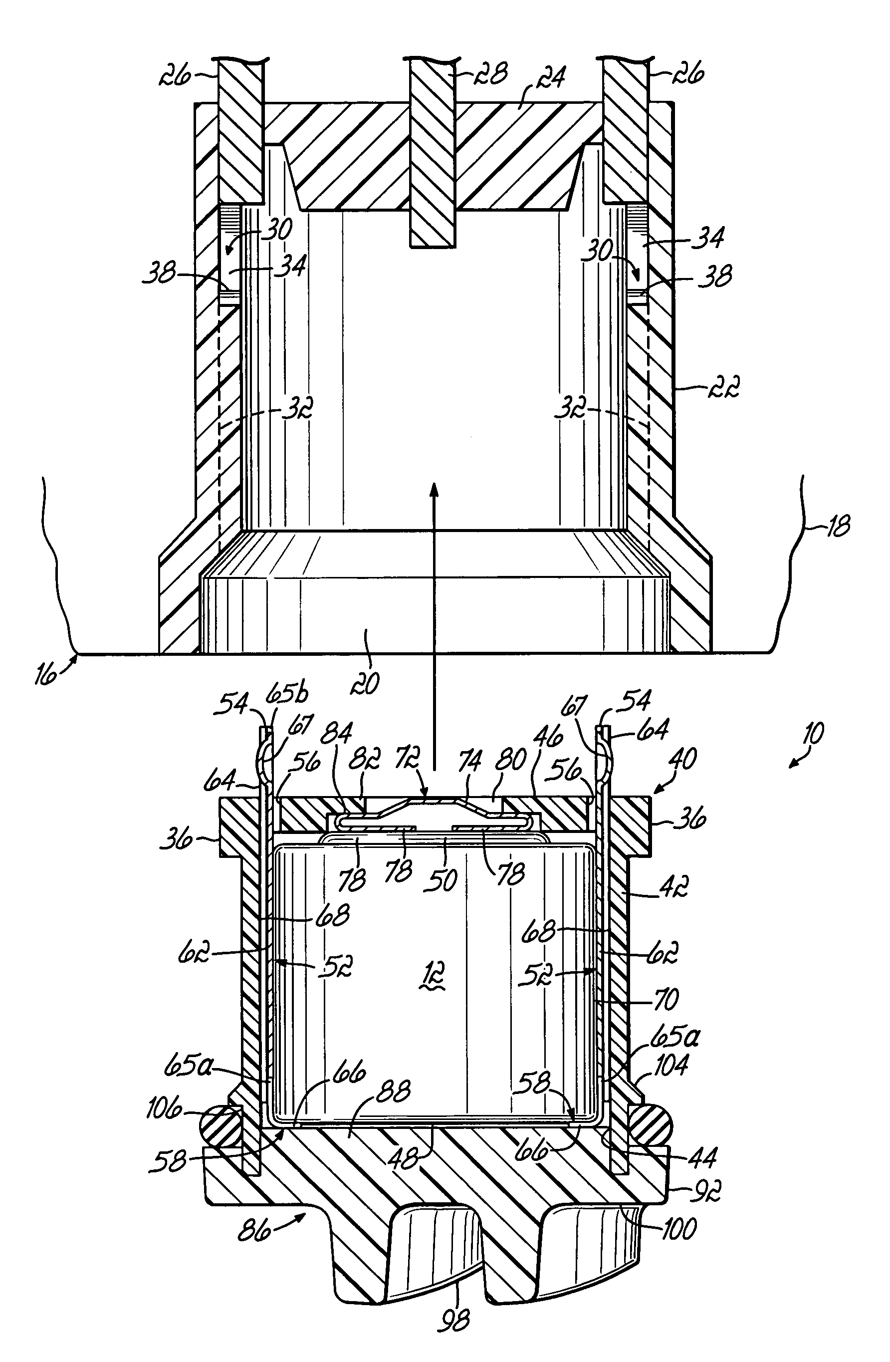
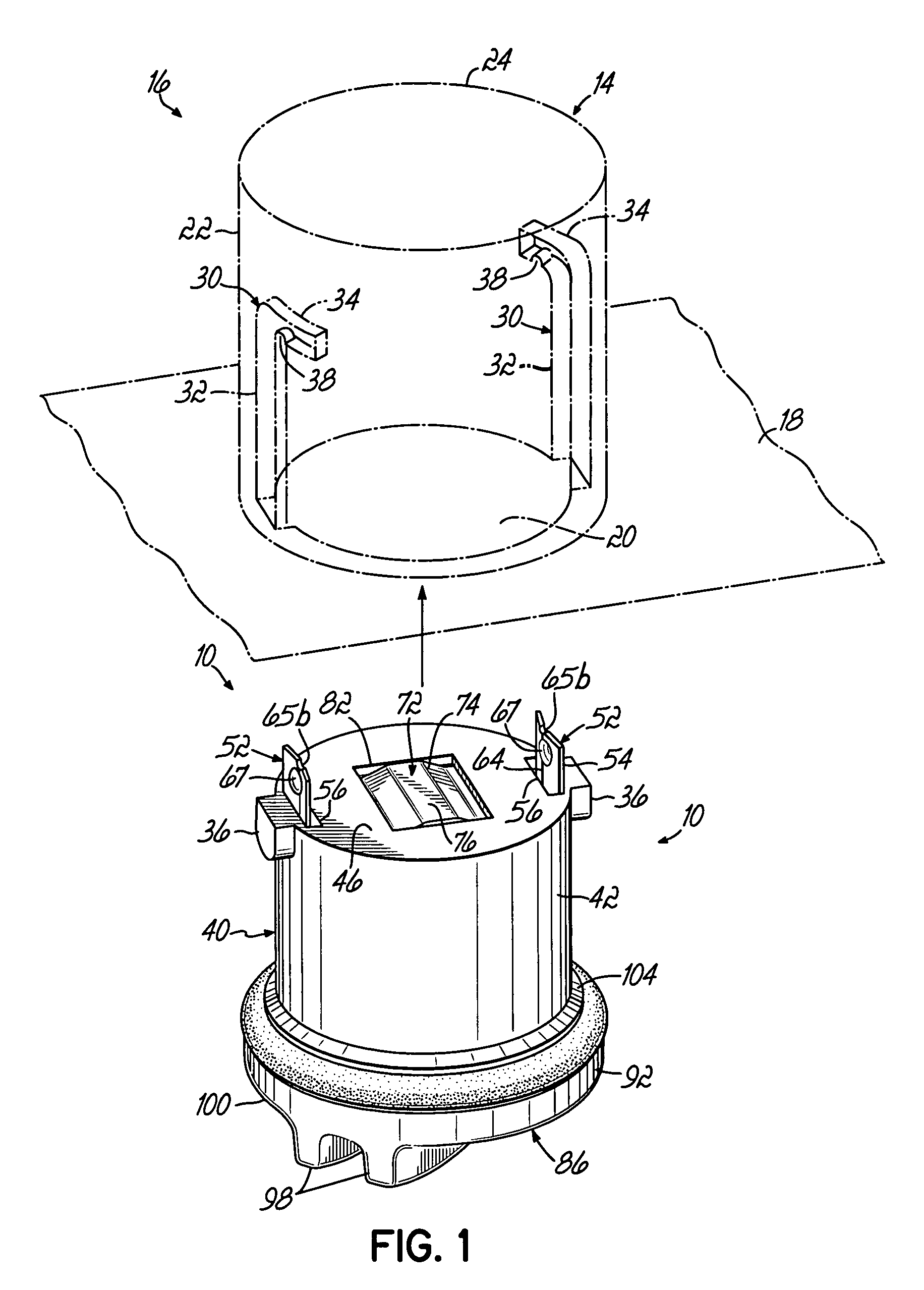
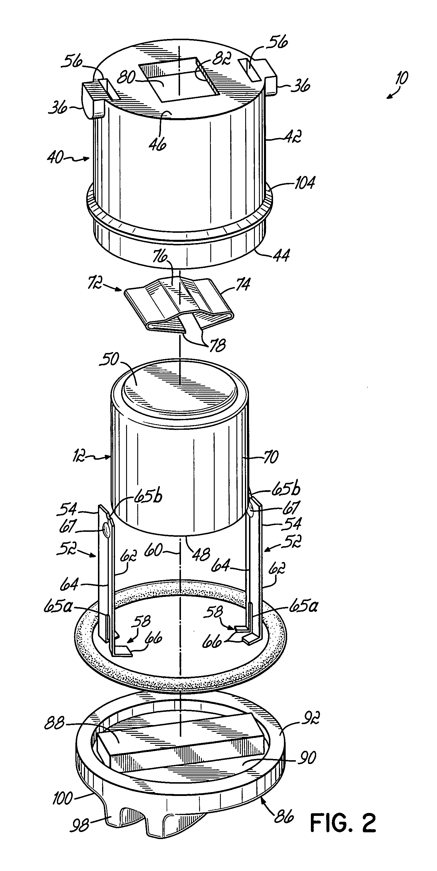
[0026]Referring to the figures, and to FIG. 1 in particular, a battery pack assembly 10 is shown in accordance with the principles of the present invention. As will be described in greater detail below, the battery pack assembly 10 is a self-contained unit having a battery 12 therein which is configured to be removably insertable into a receptacle 14 of an electronic device 16, such as, by way of example, an electronic battery-powered receiver used in an animal confinement system. The receiver 16 is carried by an animal and is responsive to a boundary signal emitted from a transmitter (not shown) of the animal confinement system to generate a stimulus, such as an electrical shock, to the animal through electrodes (not shown) when the boundary signal is received. In this way, the animal is contained within the boundary defined by the boundary signal. The present invention will be described by way of example in connection with use of the battery pack assembly 10 in an electronic recei...


PUM

PropertyMeasurementUnit
flexibleaaaaaaaaaa
electrical poweraaaaaaaaaa
rotationaaaaaaaaaa

Abstract

A battery pack assembly is provided for supplying electrical power to an electronic device, such as an electronic receiver of an animal confinement system. The battery pack assembly is removably insertable within a receptacle of the electronic receiver to electrically connect a battery contained within the battery pack assembly to internal electronics of the electronic receiver.

Description

FIELD OF THE INVENTION[0001]The present invention relates generally to battery devices for supplying electrical power and, more particularly, to a removable battery pack assembly for supplying electrical power to an electronic device.BACKGROUND OF THE INVENTION[0002]Removable battery pack assemblies are commonly used with electronic devices to provide electrical power from a battery to electronic circuitry of the device. Typical battery pack assemblies may contain a standard lithium cell battery therein which, over time, may need to be removed from the electronic device and replaced. The electronic device typically includes a receptacle which is configured to receive the battery pack assembly therein. When fully inserted into the receptacle, the battery pack assembly facilitates electrical contact between the battery and the internal electronics within the electronic device.[0003]Battery pack assemblies are oftentimes used in animal confinement systems, for example. In such systems,...

Claims


Application Information

Patent Timeline
Patent Type & Authority Patents(United States)
IPC IPC(8): H01M2/10H01M50/559
CPCH01M2/30H01M2/105Y02E60/10H01M50/213H01M50/559
Inventor TOUCHTON, SCOTT F.CHESLOCK, EDWARD P.
Owner PERIMETER TECH
Why Eureka
Try Eureka