Contact and electrical connecting apparatus

a technology of electrical connection and contact pin, which is applied in the direction of coupling contact members, coupling device connections, instruments, etc., can solve the problems of contact failure, inability to slide accurately and favorably, so as to achieve reliable electrical contact

Active Publication Date: 2014-05-13
NIHON MICRONICS
View PDF15 Cites 10 Cited by
  • Summary
  • Abstract
  • Description
  • Claims
  • Application Information

AI Technical Summary

Benefits of technology

[0019]In the contact and the electrical connecting apparatus according to the present invention, the respective plungers are slidably supported in a stable manner without fluctuation, and reliable electrical contact is achieved.

Problems solved by technology

However, in this case, since the respective supporting bar portions 4A are just supported by the coil spring 3, there is a problem in which the respective supporting bar portions 4A become loose and unstable each other due to changes in inside diameter of the coil spring 3 caused by elasticity, and thus the respective contact pins 2 cannot slide accurately and favorably.
In particular, operations of the respective contact pins 2 require high accuracy when size reduction of the contact 1 is advanced along with high integration of a circuit, but a structure in which the respective supporting bar portions 4A are supported by the coil spring 3 causes a problem in which the respective contact pins 2 cannot slide accurately and favorably, and a contact failure may occur.
Also, in the contact 7 in Patent Document 2, the inside diameter of the spring 9 is set to a dimension that allows the core bar portion 8C of the plunger 8 to be inserted to be movable up and down, but there is a problem in which the plunger 8 becomes loose and unstable due to changes in inside diameter of the spring 9 caused by elasticity and cannot slide accurately and favorably.

Method used


Image

  • Contact and electrical connecting apparatus
  • Contact and electrical connecting apparatus
  • Contact and electrical connecting apparatus

Examples


modification examples

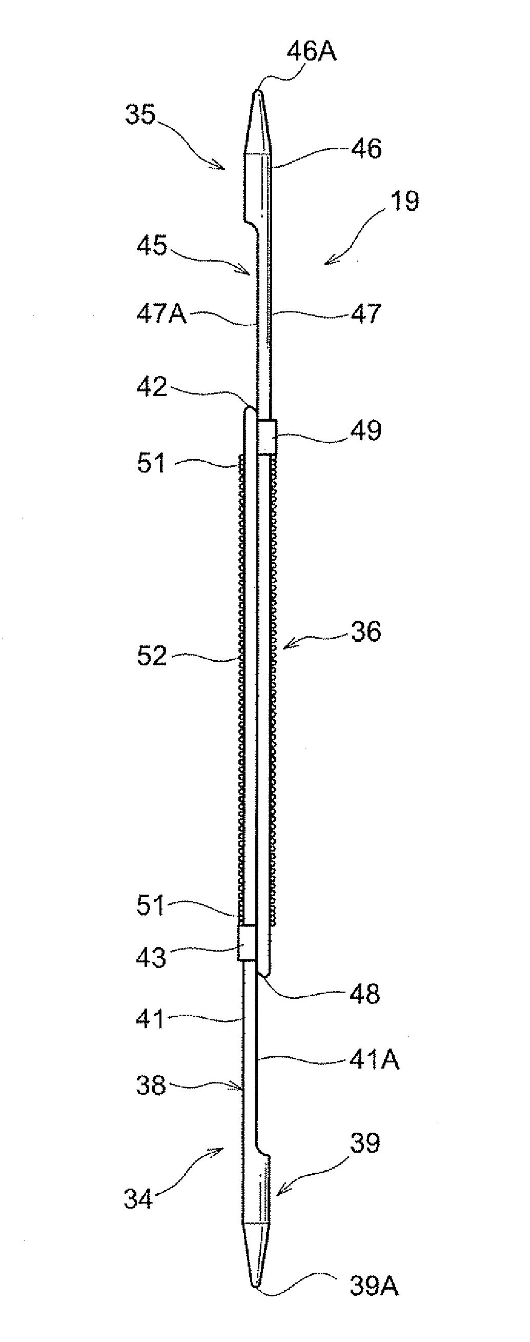
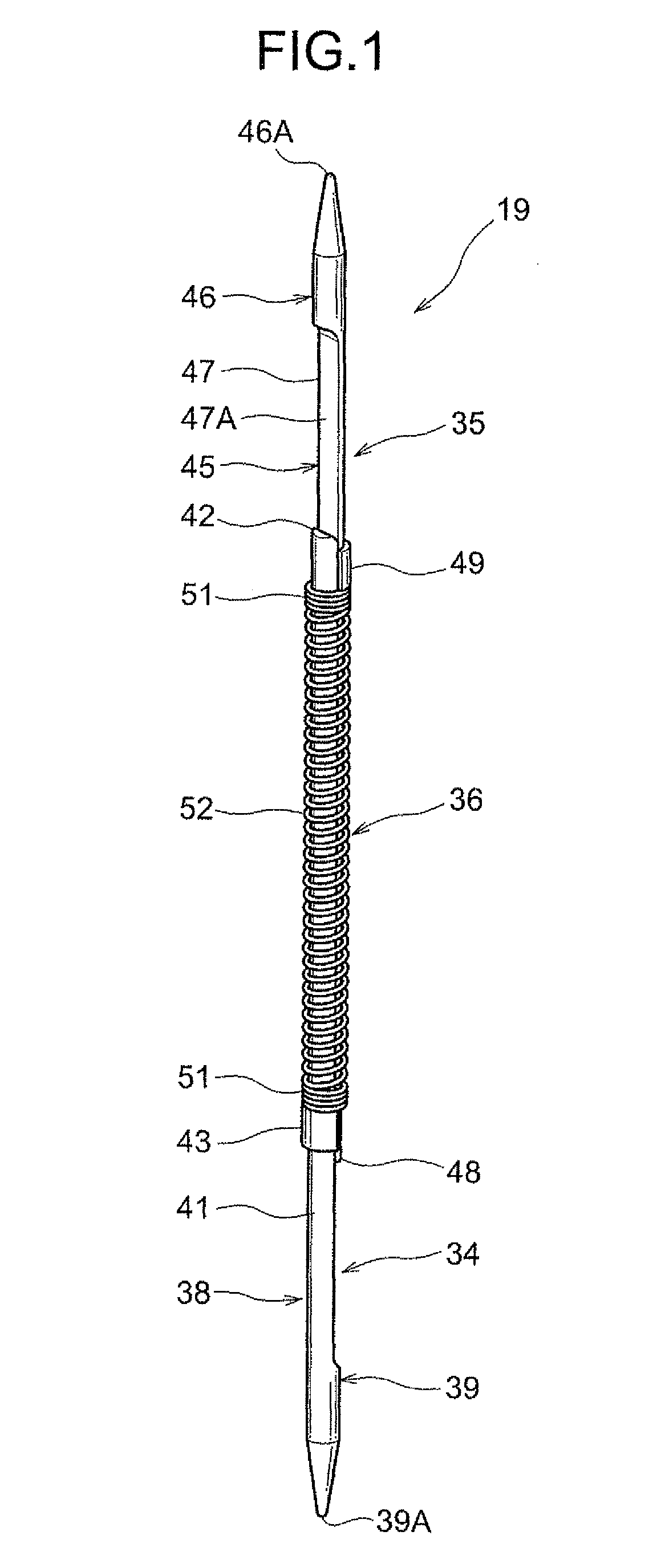
[0083]Although the board-side plunger 34 and the device-under-test-side plunger 35 are formed to have circular cross-sections and semi-circular cross-sections in the aforementioned embodiments, they may be formed to have polygonal cross-sections. For example, as shown in FIG. 21, the tip end portions 39 and 46 may have cross-sections formed in hexagonal shapes while the sliding portions 38 and 45 may have cross-sections formed in halved shapes of the aforementioned hexagonal shapes. Also, as shown in FIG. 22, the tip end portions 39 and 46 may have cross-sections formed in quadrangular shapes while the sliding portions 38 and 45 may have cross-sections formed in halved shapes of the aforementioned quadrangular shapes. Further, they may be formed in other polygonal shapes. These cases can exert similar effects to those of the aforementioned embodiments.

Industrial Applicability

[0084]The contact of the present invention can be used in general apparatuses that are brought into contact w...


PUM


Abstract

Respective plungers are slidably supported in a stable manner without fluctuation, and reliable electrical contact is achieved.In a contact of the present invention, a first plunger and a second plunger include tip end portions provided on tip end sides, slidably supported, and contacting two respective members and sliding portions provided on proximal end sides, formed in halved shapes of the respective plungers, slidably overlapped with each other, and inserted in a compression coil spring. Each of the sliding portions is set to have a length to be slidably supported together with the tip end portion of the other plunger.

Description

TECHNICAL FIELD[0001]The present invention relates to a contact that contacts an electrode provided on a wiring board, a semiconductor integrated circuit, or the like and an electrical connecting apparatus.BACKGROUND ART[0002]A contact that electrically connects to each other electrical circuits or the like of wiring boards disposed to be opposed to each other is generally known. Examples of such a contact are ones described in Patent Document 1 and Patent Document 2.[0003]A contact 1 in Patent Document 1 includes two contact pins 2 having equal shapes and a coil spring 3 as shown in FIGS. 2 and 3.[0004]The contact pin 2 mainly includes locking claws 4, a locking hole 5, a flange portion 6, and a pin tip end portion 2A. Two locking claws 4 are provided to be opposed to each other and are supported by resilient supporting bar portions 4A. This allows the two locking claws 4 to approach to and separate from each other. The locking hole 5 is a hole in which the locking claws 4 are fitt...

Claims


Application Information

Patent Timeline
Patent Type & Authority Patents(United States)
IPC IPC(8): H01R13/24
CPCG01R1/06722G01R1/0483G01R1/07371H01R13/2421G01R1/06738H01R13/24H01R33/76
Inventor HASEGAWA, YOSHIEI
Owner NIHON MICRONICS
Why Eureka
Try Eureka