Socket contact

A socket contact and contact piece technology, applied in the direction of contact parts, contact piece manufacturing, connecting device components, etc., can solve complex manufacturing, expensive and other problems, and achieve the effect of less wear and tear

Active Publication Date: 2015-09-16
HARTING ELECTRIC GMBH & CO KG
View PDF9 Cites 10 Cited by
  • Summary
  • Abstract
  • Description
  • Claims
  • Application Information

AI Technical Summary

Problems solved by technology

[0009] However, a disadvantage of such socket contacts is that they are complex and expensive to manufacture

Method used


Image

  • Socket contact
  • Socket contact
  • Socket contact

Examples


Embodiment Construction

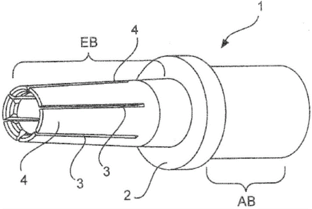
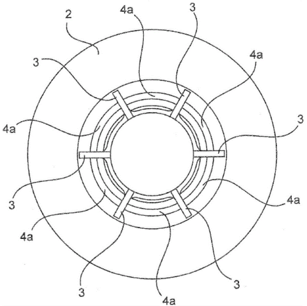
[0033] figure 1 A perspective view of an exemplary embodiment of a socket contact 1 according to the invention is shown. The socket contact 1 basically consists of a hollow cylinder made of an electrically conductive material such as sheet metal. Alternatively, the receptacle contacts may be machined from solid material. The hollow cylinder is interrupted by a substantially centrally arranged circumferential thickening 2 separating the connection area AB and the insertion area EB from each other. This thickening 2 serves to position the socket contact in the insulating body of the plug-in connector.

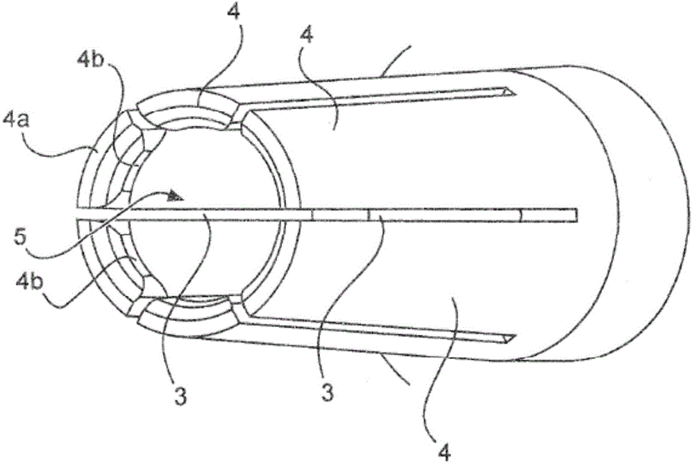
[0034] In the insertion area EB of the hollow cylinder, axial grooves 3 are introduced to form individual elastic arms 4 . The ends 4a of the spring arms 4 are bent towards each other in the radial direction. In the exemplary embodiment shown here, the end 4 a of the spring arm 4 surrounds the insertion opening 5 of the socket contact 1 .

[0035] At the end 4 a of the sprin...


PUM


Abstract

The contact (1) has two spring arms (4) whose ends comprise contact regions, where the contact is formed from a hollow cylinder. An axial slot (3) is brought into the hollow cylinder, where the two spring arms are formed at the axial slot. The contact regions are designed as a truncated pyramid that is formed with a curved top surface, where the curved top surface of the truncated pyramid produces two touching contacts with a pin contact. The spring arms are flexed to each other in a radial direction and exhibit a wall thickness that is varied in an axial direction.

Description

technical field [0001] The invention relates to a socket contact according to the preamble of claim 1 . Furthermore, the invention relates to a method for producing a socket contact according to claim 8 . Background technique [0002] Such socket contacts are used to produce electrical contacts with pin contacts. [0003] The electrical conductors can be connected directly to the socket contacts and pin contacts. Crimp connection techniques are often used to connect conductors to socket contacts or pin contacts. [0004] DE 102010020346 A1 shows a contact socket with individual spring arms. The socket is manufactured from solid material. Such a contact socket with associated pin contacts can provide high contact force. This contact force remains constant even after several plug-in operations. [0005] EP 0133377 A2 shows a socket contact with two contact blades. The contact piece is V-shaped and thus has two contact pieces which come into contact with a contact pin. ...

Claims


Application Information

Patent Timeline
Patent Type & Authority Applications(China)
IPC IPC(8): H01R13/11H01R43/16
CPCH01R13/111H01R43/16Y10T29/49206H01R13/187
Inventor S·格里彭施特罗T·迈豪斯F·博格曼H·考灵B·布兰克
Owner HARTING ELECTRIC GMBH & CO KG
Why Eureka
Try Eureka