Capacitor arrangement and method for operating a capacitor arrangement

a capacitor and capacitor technology, applied in the direction of electrolytic capacitors, electrical apparatus construction details, transportation and packaging, etc., can solve the problems of power loss particularly in power semiconductors, and achieve the effects of low-inductivity connection, low-inductivity connection, and good conductive connection

Active Publication Date: 2016-09-15
ROBERT BOSCH GMBH
View PDF3 Cites 9 Cited by
  • Summary
  • Abstract
  • Description
  • Claims
  • Application Information

AI Technical Summary

Benefits of technology

[0012]According to one embodiment, the connection arrangement further comprises an isolation medium which is disposed between the first connection element and the second connection element. This isolation medium preferably relates to an electrically insulating film. This can, for example, relate to a plastic film consisting of a flexible plastic material. By means of such an isolation medium between the individual connection elements, said individual connection elements can be disposed at a small spatial distance from one another without a short circuit occurring between said individual connection elements. As a result, a particularly efficient, low-inductivity connection between DC link capacitor and switching module is made possible. In so doing, the electrically conductive films and the isolation medium are connected to one another, for example adhesively bonded to one another.
[0013]In one embodiment, the first connection element comprises a multiplicity of electrically conductive films, and the second connection element comprises a multiplicity of electrically conductive films. By using a multiplicity of electrically conductive films for each of the connection elements, a particularly good conductive and hence low-resistance and low-inductivity connection between DC link capacitor and switching module is made possible.

Problems solved by technology

When operating such a power electronic system, a power loss occurs particularly in the power semiconductors.

Method used


Image

  • Capacitor arrangement and method for operating a capacitor arrangement
  • Capacitor arrangement and method for operating a capacitor arrangement
  • Capacitor arrangement and method for operating a capacitor arrangement

Examples


Embodiment Construction

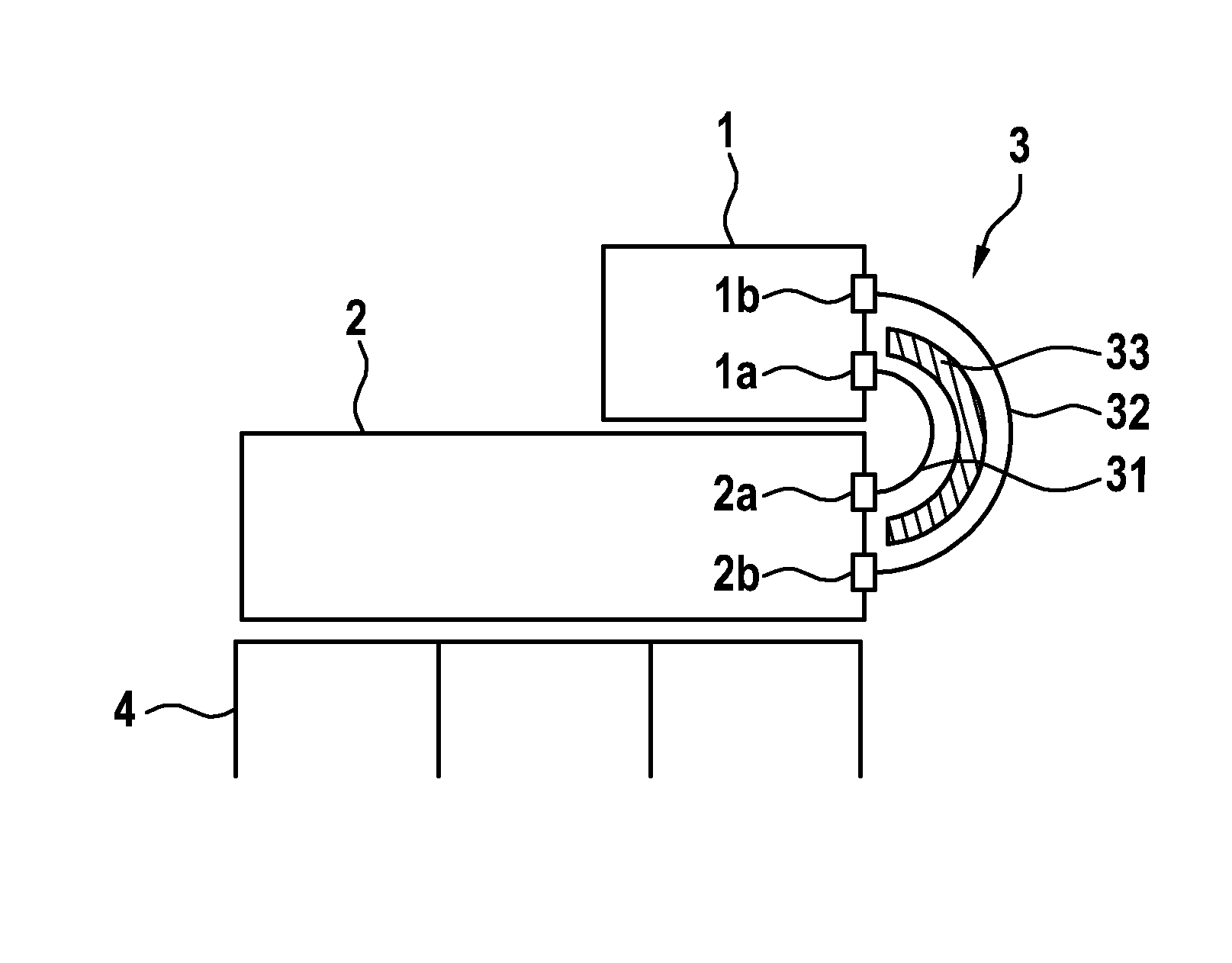
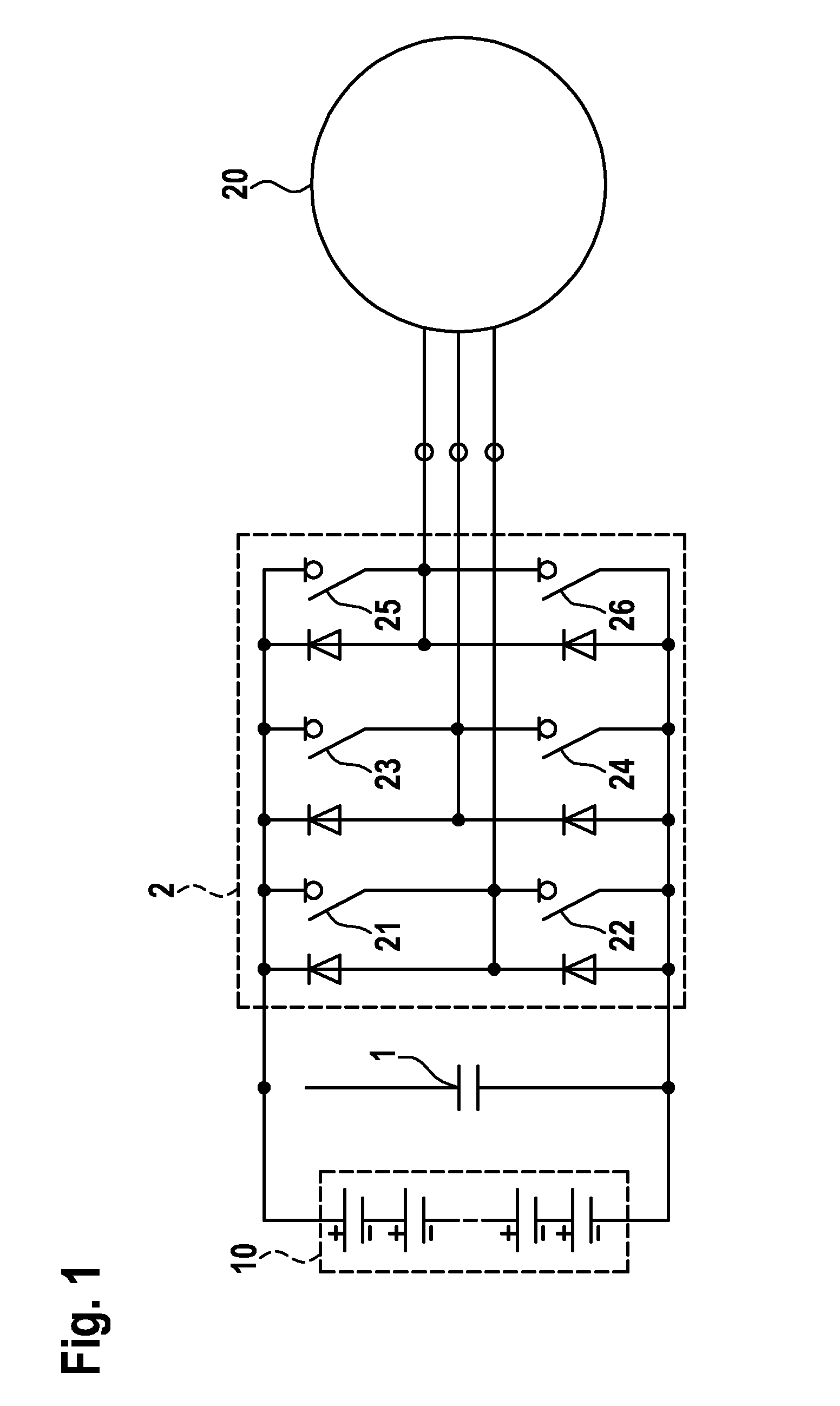
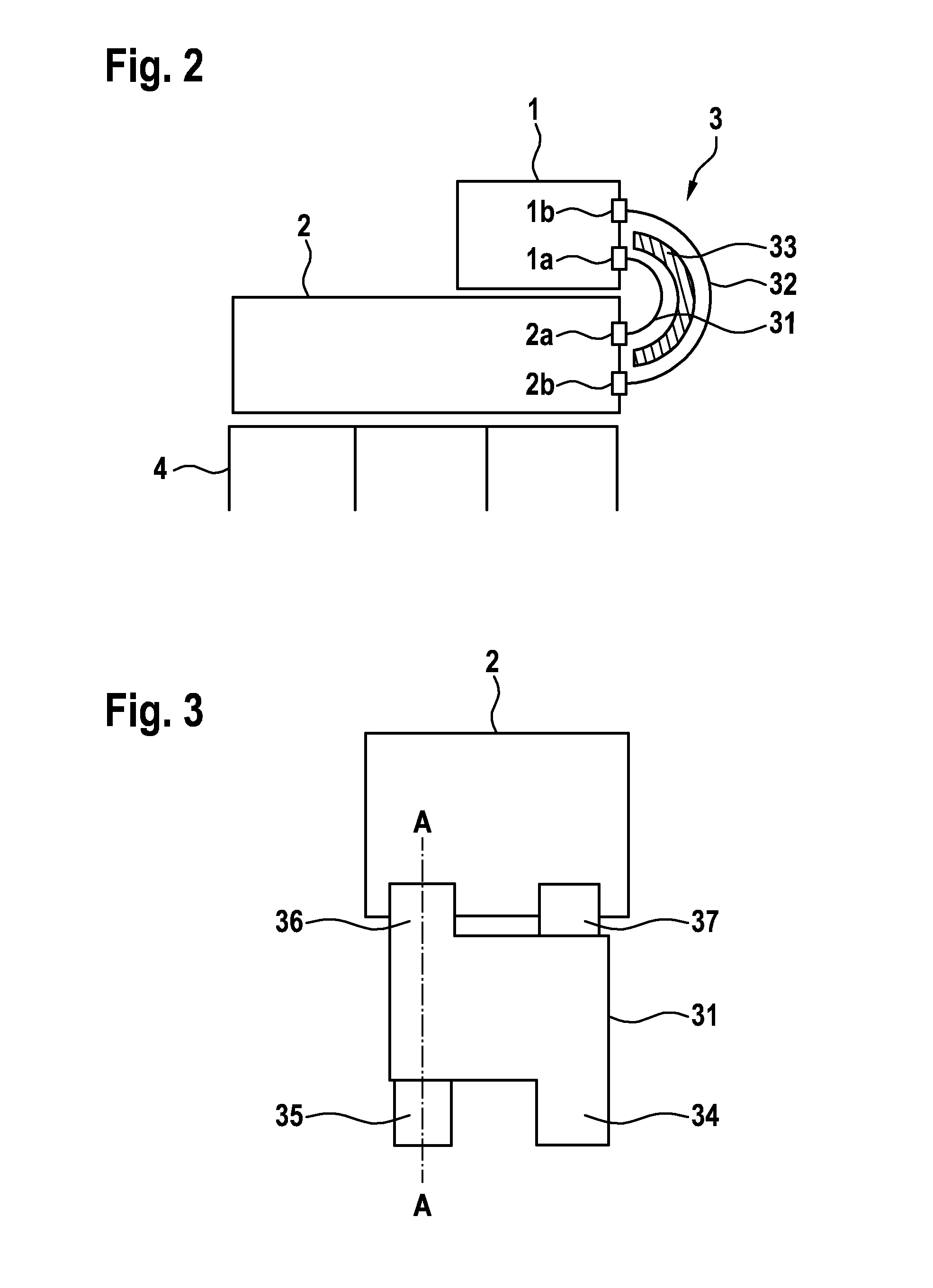
[0025]FIG. 1 shows a schematic depiction of a basic circuit diagram of a three-phase inverter circuit. The power electronic system is supplied by a storage battery 10. The DC voltage provided by this storage battery 10 is buffered by a DC link capacitor 1 and is subsequently supplied to a switching module 2 comprising a plurality of power semiconductors 21 to 26. By means of a corresponding control of the power semiconductors 21 to 26, the DC voltage is thereby converted into an AC voltage and is supplied to an electrical machine 20.

[0026]Although the capacitor arrangement is described below with reference to the previously described circuit arrangement of a drive system, the capacitor arrangement according to the invention is not limited to this application. The inventive capacitor arrangement can in fact be used for all applications, in which a DC link capacitor is to be electrically coupled to a switching module. Such applications can, for example, be stationary applications, suc...


PUM


Abstract

The present invention provides a low-inductivity and mechanically stable connection between a DC link capacitor and a switching module for a power electronic system. To this end, the DC link capacitor and the switching module are connected to each other via an electrically conductive, flexible connection arrangement of electrically conductive strips or films. The individual strips or films are spaced from each other via suitable isolation media.

Description

BACKGROUND OF THE INVENTION[0001]The present invention relates to a capacitor arrangement and a method for operating a capacitor arrangement.[0002]Power electronic systems are increasingly being used in stationary applications, such as, for example, in wind turbines, as well as in mobile applications, such as, for example, in electric and hybrid vehicles. These power electronic systems, for example, enable a connected electrical machine to be operated at a variable rotational speed or to generate an output voltage which deviates from an input voltage. As a rule, said power electronic systems are supplied with a DC voltage which is supplied via a pulse width modulated inverter, also referred to as inverter. A so-called DC link, via which the power electronic system is connected to the DC voltage source, is characteristic for such systems. In order for the DC link to also be able to dynamically provide the currently required power, the DC link is buffered with a DC link capacitor. Sai...

Claims


Application Information

Patent Timeline
Patent Type & Authority Applications(United States)
IPC IPC(8): H02M7/12H05K7/20H02M7/00
CPCH02M7/12H05K7/209H02M7/003H01G9/008H01G9/14H01G9/26Y02T10/70H05K7/14329H05K7/1432
Inventor FEUERSTACK, PETER
Owner ROBERT BOSCH GMBH
Why Eureka
Try Eureka