Multi-phase interleaving isolated DC/DC converter

a converter and multi-phase technology, applied in the field of dc/dc converters, can solve the problems of increasing the conduction loss of conventional converters, increasing the cost and footprint, and severe thermal problems, so as to reduce the conduction loss of synchronous rectifier and transformer winding, the power density of the converter can be greatly increased, and the output current and power density increase

Inactive Publication Date: 2005-09-13
VIRGINIA TECH INTPROP INC
View PDF5 Cites 81 Cited by
  • Summary
  • Abstract
  • Description
  • Claims
  • Application Information

AI Technical Summary

Benefits of technology

[0011]Compared to a conventional phase-shift full bridge converter with Current-Doubler rectifier, the proposed zero-voltage switching multi-phase interleaving isolated DC / DC converter reduces the synchronous rectifier conduction loss as well as the transformer winding loss. Furthermore, the proposed transformer structure is compact so the power density of the converter can be greatly increased. Analysis and experimental results show that the proposed topology demonstrates great advantages when the converter output current goes higher and voltage goes lower as demanded by future microprocessors.
[0012]The present invention can significantly increase the output current and power density of a 48 V DC / DC isolated converter, such as a DC / DC brick converter for telecommunication, without adding much cost. Furthermore, it can be widely used in the field of low voltage high current applications such as voltage regulator modules for microprocessors.
[0013]The proposed multi-phase interleaving isolated DC / DC converter has many useful aspects. One aspect of the present invention is that it achieves zero voltage switching for the primary side switches, which not only reduces the high frequency switching loss, but also attenuates EMT noise. The phrase, zero-voltage, refers to the complete absence of voltage or the lowest voltage in a circuit to which all other voltages are referred. The present invention also exhibits reduced synchronous rectifier conduction loss, reduced transformer winding loss, and reduced transformer core loss. Another aspect of the present invention is a compact transformer structure as compared with distributed magnetics. Furthermore, the present invention results in reduced output ripple current when compared with current-doubler rectifiers. The present invention results in a low cost solution for higher output current applications.
[0014]The circuit of the present invention is simple and highly efficient. It may be used in the field of low voltage-high current applications, such as 48V power pods for microprocessors and 48V DC / DC brick converters for telecommunication.

Problems solved by technology

As current goes to 130 A, and even higher, the total conduction loss of conventional converters is significantly increased thereby causing severe thermal issues.
These solutions, however, typically result in higher cost and footprint increases while the power density decreases.
Additionally, more device means more driving loss.
These issues pose substantial challenges for future high current low voltage DC / DC converters used in microprocessors.

Method used


Image

  • Multi-phase interleaving isolated DC/DC converter
  • Multi-phase interleaving isolated DC/DC converter
  • Multi-phase interleaving isolated DC/DC converter

Examples


Embodiment Construction

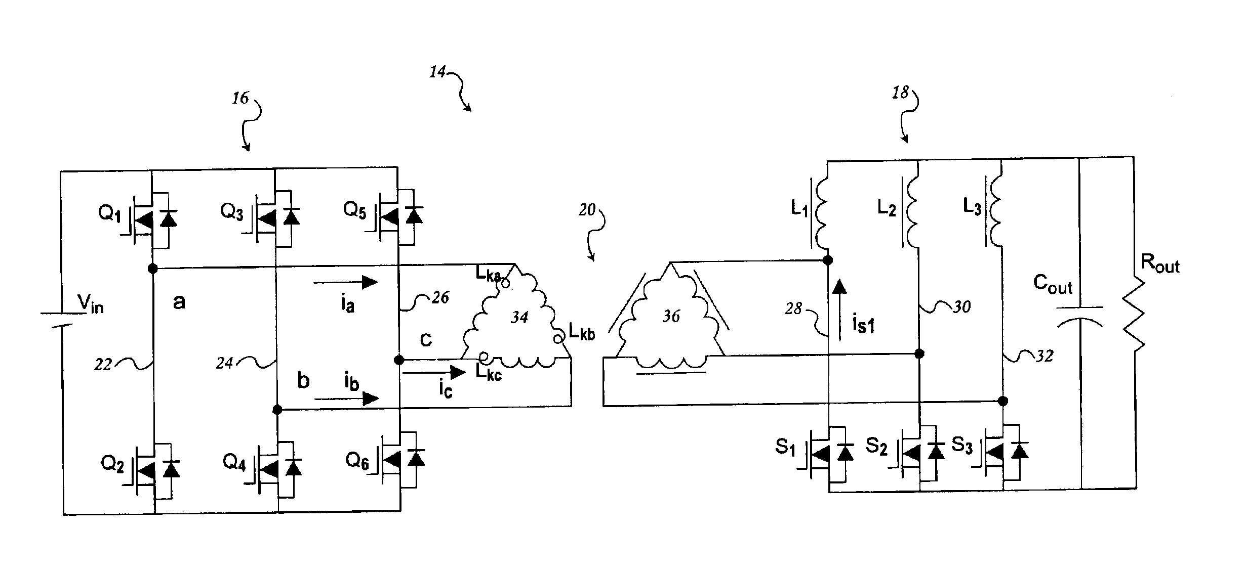
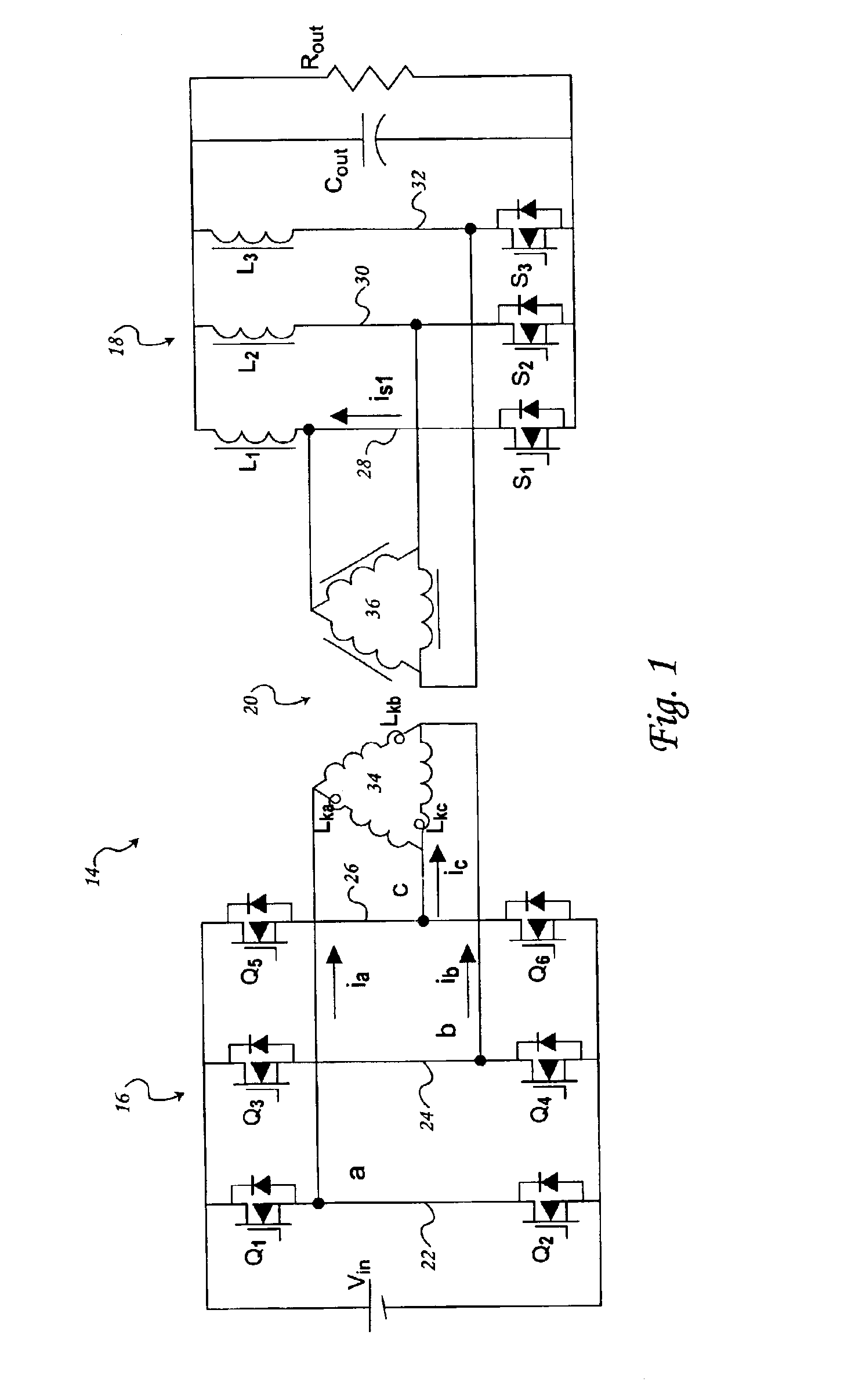
[0032]The circuit diagram for a zero-voltage switch (ZVS) current tripler DC / DC converter 14, according to the present invention, is depicted in FIG. 1. The converter of the present invention converts an input voltage into an output voltage. In order to simplify the analysis of the converter, it is assumed that the circuit operation is in steady state, the output filter inductors are large enough to be considered a current source, all devices are ideal, and the transformer magnetizing current is neglected.

[0033]The DC / DC converter 14 has a transformer 20, a primary side 16 connected to a power source, denoted Vin, and a secondary side 18 connected to an output capacitor Cout and an output load, denoted Rout. Together, the output capacitor Cout and the output load Rout are referred to herein as an output filter. The transformer 20 has a primary winding 34 connected to the primary side 16 and a secondary winding 36 connected to the secondary side 18. Each winding is a tertiary winding...


PUM


Abstract

A converter has a transformer with primary and secondary windings each having n coils in a series-series arrangement connected to primary and secondary sides. The primary side has n primary legs each having a top switch and a bottom switch and connected to the primary winding therebetween. The secondary side has n secondary legs, each secondary leg has a synchronous rectifier switch and an output filter inductor connected to the secondary winding therebetween. A complimentary control for the primary side comprising a gate driver transformer with primary winding in series with a DC blocking capacitor connected to a drain and a source of the top switch of each primary leg, and a gate drive transformer, for each primary leg, with secondary winding containing a leakage inductor and in series with a DC blocking capacitor and a damping resistor connected to gate and source of the secondary side synchronous rectifier.

Description

CROSS REFERENCE TO RELATED APPLICATIONS[0001]This application claims the benefit of U.S. Provisional Application Ser. No. 60 / 425,127, filed on Nov. 8, 2002, the contents of which are incorporated herein in its entirety by reference.FIELD OF THE INVENTION[0002]The present invention relates to a DC / DC converter and, more particularly, to a multi-phase interleaving isolated DC / DC converter and a transformer winding utilized in a DC / DC converter.BACKGROUND OF THE INVENTION[0003]It is well known that users of power supplies for microprocessors are demanding higher current and lower output voltage. As current goes to 130 A, and even higher, the total conduction loss of conventional converters is significantly increased thereby causing severe thermal issues. To lower the on resistance of a conventional synchronous rectifier, more semiconductor devices are used. Furthermore, distributed magnetics are also used to reduce transformer winding losses. These solutions, however, typically result ...

Claims


Application Information

Patent Timeline
Patent Type & Authority Patents(United States)
IPC IPC(8): H02M3/335H02M3/24
CPCH02M3/1584
Inventor XU, MINGLEE, FRED C.ZHOU, JINGHAI
Owner VIRGINIA TECH INTPROP INC
Why Eureka
Try Eureka