
Collapsible structure with self-locking mechanism and method of erecting a collapsible structure

a self-locking mechanism and collapsible technology, applied in the field of collapsible structures, can solve the problems of erecting structures that are difficult to provide structures with a cover, structures may be blown around, and structures are difficult to er

Active Publication Date: 2010-05-11
WORLD SHELTERS
View PDF34 Cites 24 Cited by
  • Summary
  • Abstract
  • Description
  • Claims
  • Application Information

AI Technical Summary

Benefits of technology

"The present invention relates to collapsible structures with self-locking mechanisms and methods of erecting them. The technical effects of the invention include the ability to erect and break down collapsible structures without needing to remove the cover, and the ability to secure the structure to the ground or base while it is being erected or broken down. This makes the collapsible structures easier to use and more stable during use."

Problems solved by technology

This makes it difficult to provide the structures with a cover as is typically provided on portable shelter type devices.
Also, because the structures during erection are typically expanded beyond the footprint of the structures in their erected condition, they are generally only secured to the ground or a base after they are finally erected.
This can make erection of the structures difficult.
For example, in windy conditions, the structures may be blown around.
This problem can be exacerbated if there is cover material on the frame because the cover material can act as a sail and make it that much more difficult to erect the structure.
During break down of these structures, the same problems occur as during erection.

Method used


Image

  • Collapsible structure with self-locking mechanism and method of erecting a collapsible structure
  • Collapsible structure with self-locking mechanism and method of erecting a collapsible structure
  • Collapsible structure with self-locking mechanism and method of erecting a collapsible structure

Examples


Embodiment Construction

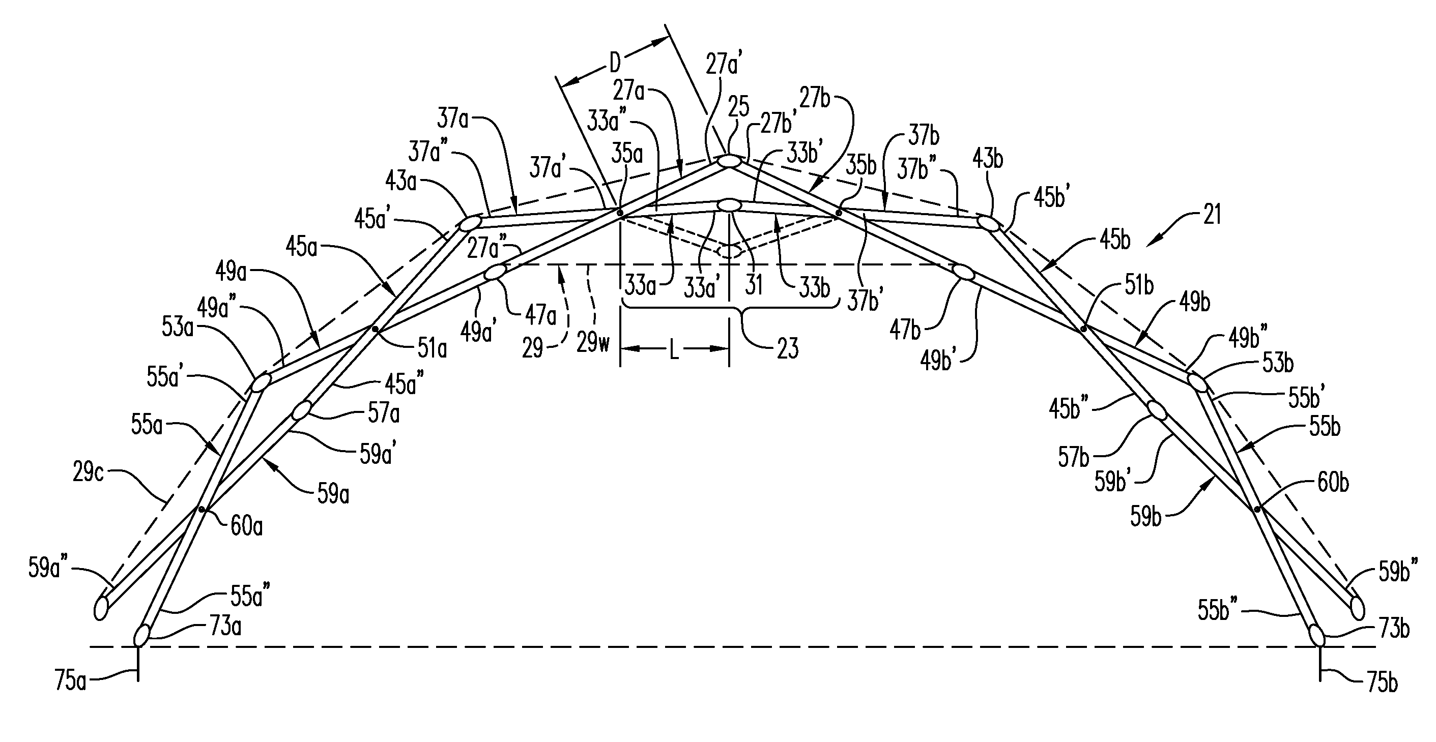
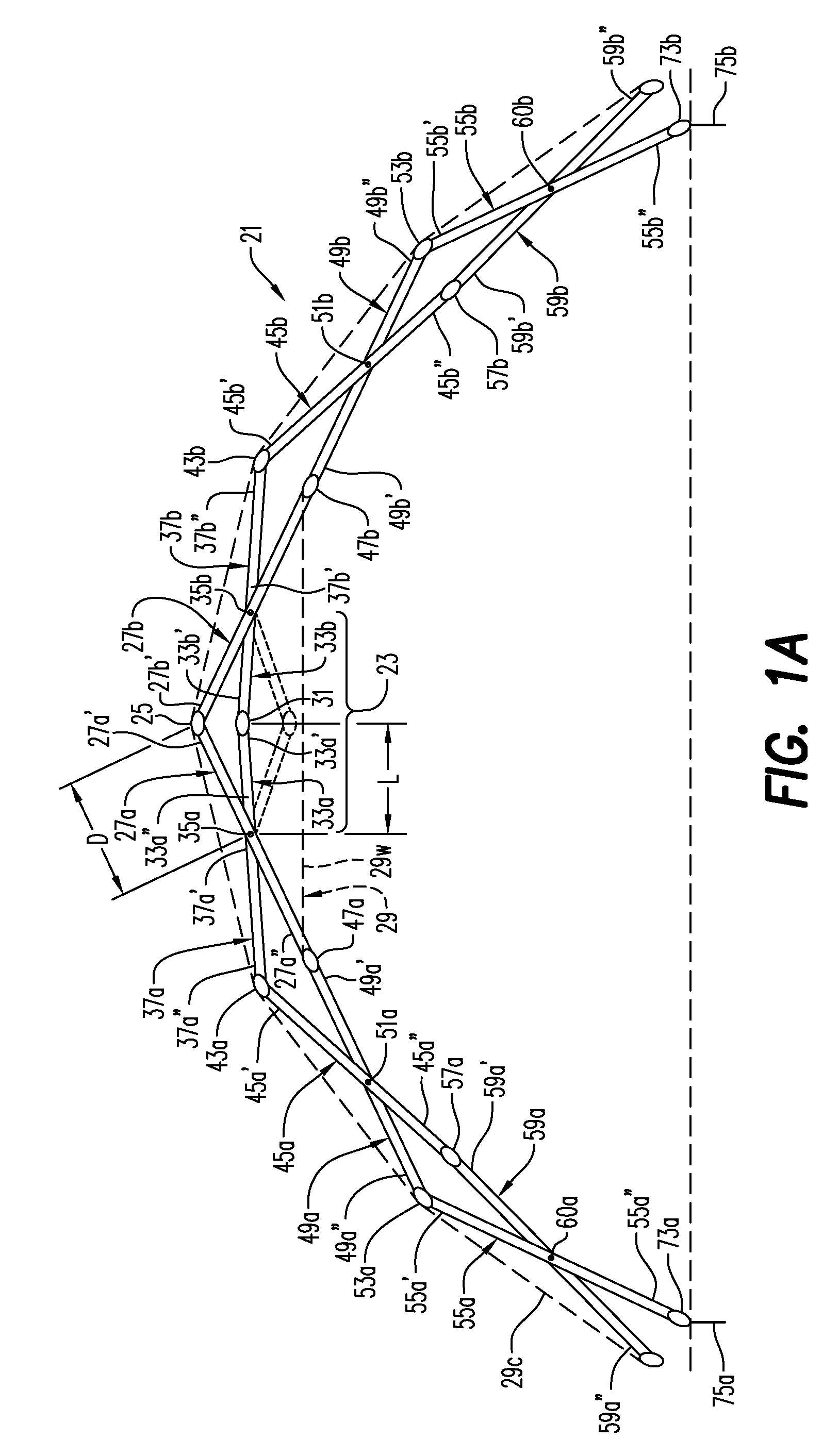
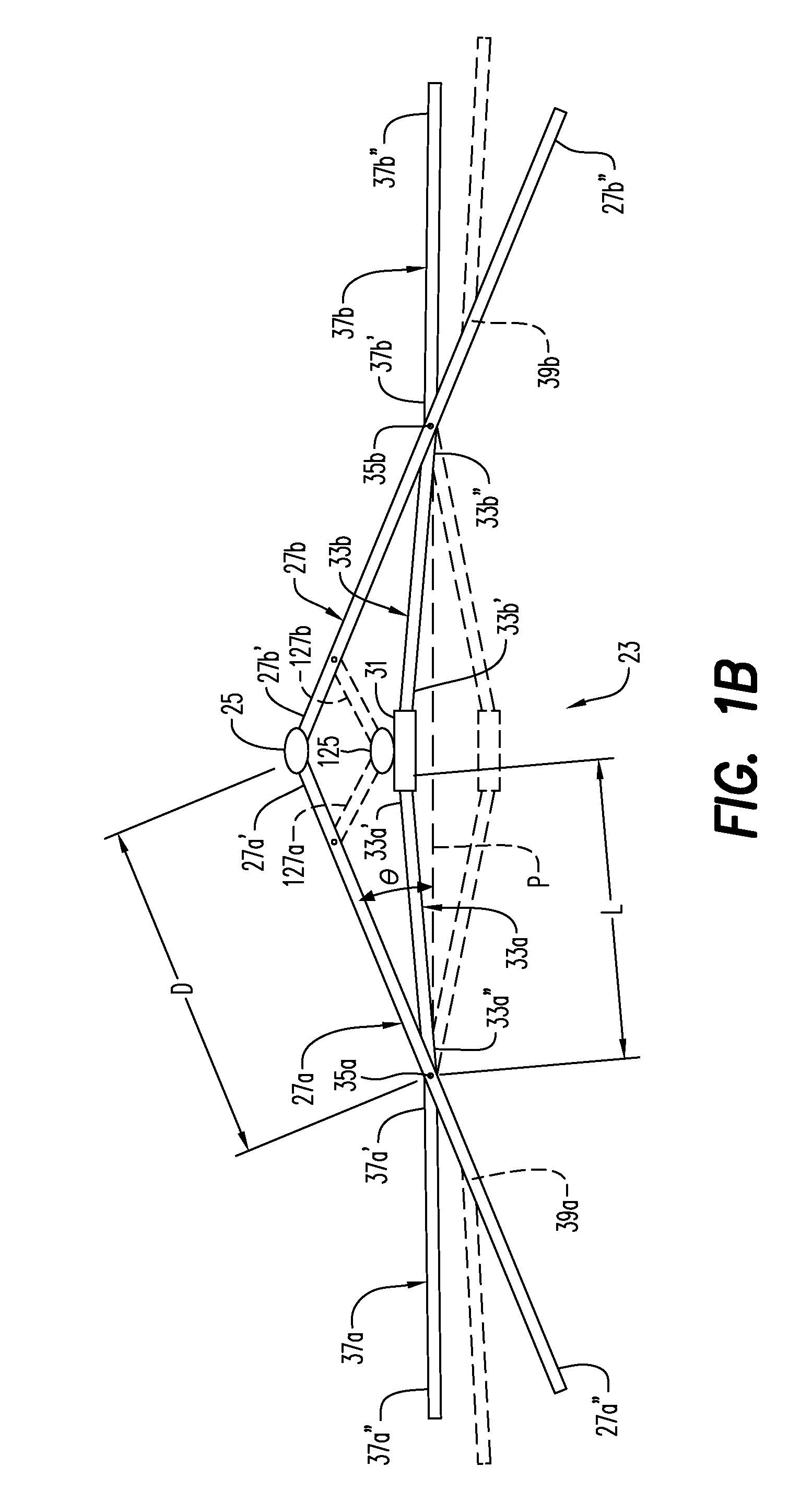
[0015]A collapsible structure 21 according to the present invention is seen in FIG. 1A. The structure 21 includes what is referred to for purposes of the present application as a self-locking mechanism 23, seen in isolated in FIG. 1B, for locking the structure in an erected condition. The structure 21 has a self-locking mechanism 23 in the sense that the self-locking mechanism 23 can maintain the structure in an erected condition by itself, without the need for additional locking structures. However, additional locking structures may be used with the structure 21, such as to provide additional strength.

[0016]The structure 21 includes a first hub 25 and at least two struts 27a and 27b pivotably connected at first ends 27a′ and 27b′ thereof to the first hub. The structure 21 includes at least two struts but will ordinarily include three or four struts (FIG. 3). Structures with more than four struts may also be provided, depending upon, for example, the shape of the structure desired. ...


PUM


Abstract

A collapsible structure with a self-locking mechanism includes a first hub, at least two struts pivotable connected at a first ends thereof to the first hub and movable relative to each another between a folded position and an expanded position, and a tension member adapted to limit pivotable movement of at least two struts such that, when in the expanded position, the at least two struts define an angle of less than 180°. The structure further includes a locking hub and at least two locking struts pivotably connected at first ends thereof to the locking hub and, at seconds ends thereof, to connection points on respective ones of the at least two struts. A method of erecting a structure is also disclosed.

Description

BACKGROUND AND SUMMARY[0001]The present invention relates to collapsible structures and, more particularly, to collapsible structures with self-locking mechanism and methods of erecting a collapsible structure.[0002]My prior U.S. Pat. Nos. 6,141,934, 5,651,228, 5,444,946, 5,274,980, 5,230,196, RE33,710, 4,970,841, 4,838,003, 4,800,663, 4,761,929, 4,747,239, 4,689,932, 4,666,102, 4,637,180, 4,579,066, 4,561,618, 4,522,008, 4,512,097, 4,473,986, 4,437,275, 4,334,660, 4,290,244, 4,280,521, 4,026,313, and 3,968,808 are incorporated by reference and show various collapsible structures and components therefor. In many collapsible structures of the general type described in these patents, in the course of erecting the structures, the structures must extend beyond the dimensions of the erected shelter. For example, in my U.S. Pat. Nos. 5,444,946 and 5,274,980, in the course of erecting the shelters, they are typically expanded laterally outward significantly past the lateral dimensions of t...

Claims


Application Information

Patent Timeline
Patent Type & Authority Patents(United States)
IPC IPC(8): E04B1/34E04H12/18E04H15/50
CPCE04H15/50
Inventor ZEIGLER, THEODORE R.
Owner WORLD SHELTERS
Learn More