Flow rate measuring apparatus having a resin plate for supporting a flow rate detecting element and a circuit board

a flow rate and measuring apparatus technology, applied in the direction of liquid/fluent solid measurement, volume metering, instruments, etc., can solve the problems of flow rate detection error and flow rate detection error

Inactive Publication Date: 2010-05-11
MITSUBISHI ELECTRIC CORP
View PDF25 Cites 32 Cited by
  • Summary
  • Abstract
  • Description
  • Claims
  • Application Information

AI Technical Summary

Benefits of technology

[0018]According to the flow rate measuring apparatus of the present invention, there are obtained the following advantageous effects. That is, flow rate detection errors resulting from a difference in temperature between the inside and outside of piping can be reduced, and the occurrence of a break or disconnection of an electric line or lead resulting from the vibration of the piping can be reduced.

Problems solved by technology

In case where such a kind of flow rate measuring apparatus is applied to a fuel injection system of such an automotive internal combustion engine, there arises the following problem.
That is, the heat of the intake pipe is transmitted to the heat generation resistor 1 and the thermally sensitive resistor 2 through the metal base 5 and the support terminal 35, thus resulting in a cause of a flow rate detection error.
Moreover, similarly, in the flow rate measuring apparatus described in the above-mentioned second patent document, too, there has been the following problem.
That is, the heat of the intake pipe or the heat due to own heat generation of the circuit board 6 in the module housing 4 installed in the intake pipe is transmitted to the heat generation resistor 7 and the temperature sensitive resistor 8 through the metal base 5 and the support terminal 2, thus resulting in a cause of a flow rate detection error.

Method used


Image

  • Flow rate measuring apparatus having a resin plate for supporting a flow rate detecting element and a circuit board
  • Flow rate measuring apparatus having a resin plate for supporting a flow rate detecting element and a circuit board
  • Flow rate measuring apparatus having a resin plate for supporting a flow rate detecting element and a circuit board

Examples


embodiment 1

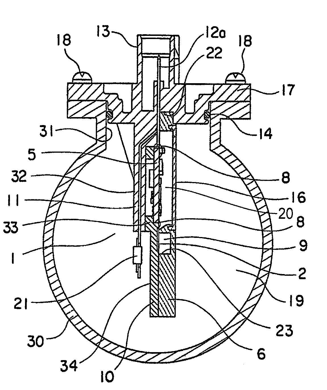
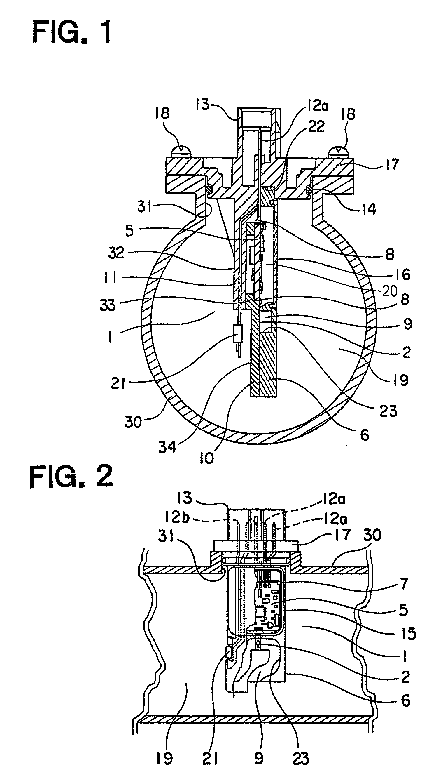
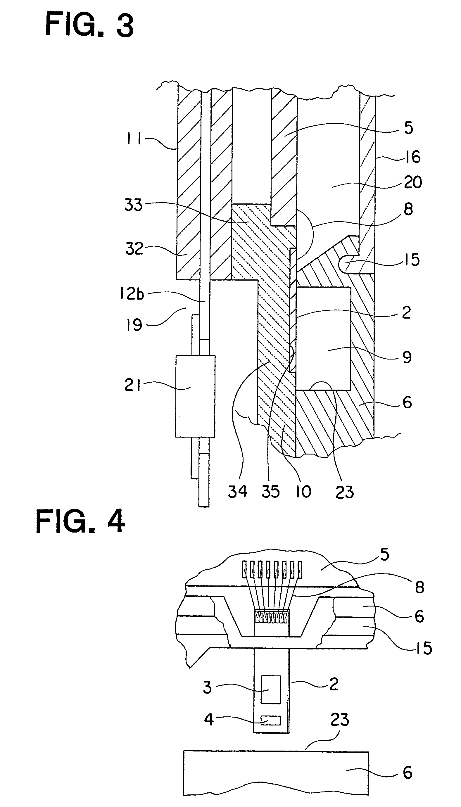
[0052]Referring to the drawings and first to FIG. 1, there is shown a cross sectional side view of a flow rate measuring apparatus according to a first embodiment of the present invention. FIG. 2 is a partially cut-away front elevational view of the flow rate measuring apparatus of FIG. 1. FIG. 3 is an enlarged view of essential portions of the flow rate measuring apparatus of FIG. 1, and FIG. 4 is an enlarged view of essential portions of the flow rate measuring apparatus of FIG. 2.

[0053]An intake pipe 30 of the internal combustion engine has an insertion hole 31 formed therein, and the flow rate measuring apparatus, generally designated at reference numeral 1, is inserted into the insertion hole 31 and installed on the intake pipe 30.

[0054]This flow rate measuring apparatus 1 includes a base 11, a plate 10 that is attached or bonded to the base 11 along a flow direction of air in the form of a fluid to be measured, a flow rate detection element 2 that is formed on the plate 10 so ...

embodiment 2

[0081]FIG. 10 is a cross sectional side view that shows a flow rate measuring apparatus 1 according to a second embodiment of the present invention, and FIG. 11 is a partially cut-away front elevational view of the flow rate measuring apparatus 1 of FIG. 10.

[0082]In the second embodiment of the present invention, a base 11 and a plate 10 are integrally formed with each other by the use of the same PBT resin. The other construction of this second embodiment is similar to that of the first embodiment.

[0083]According to the flow rate measuring apparatus of this second embodiment, advantageous effects similar to those of the first embodiment can be achieved. In addition, the process of positioning or aligning the plate 10 and the base 11 with each other becomes unnecessary, and at the same time, based on the thus integrated component parts of the plate 10 and the base 11, it is possible to assemble the respective component parts including the circuit board 5, the housing 6 and the cover...

embodiment 3

[0084]FIG. 12 is a cross sectional side view that shows a flow rate measuring apparatus 1 according to a third embodiment of the present invention, and FIG. 13 is a partially cut-away front elevational view of the flow rate measuring apparatus 1 of FIG. 12.

[0085]In this third embodiment of the present invention, a base main body 32 of a base 11 and a flange 17 are formed as separate members, respectively. The base main body 32, a plate 10, a circuit board 5, a housing 6 and a cover 16, which are laminated one over another, have their relative positions to the flange 17 located at a radially outer side thereof in comparison with the first embodiment. The other construction of this third embodiment is similar to that of the first embodiment.

[0086]In this third embodiment, the same effects as those in the first embodiment can be achieved, and the wire 8 electrically connecting between the circuit board terminal 12a and the circuit board 5 is arranged at a fixed side of the vibration of...


PUM


Abstract

A flow rate measuring apparatus can reduce flow rate detection errors resulting from a temperature difference between an inside and an outside of piping. A base has a base main body which is formed at its base end with a connector protruding to the outside of the piping, and a flange which is formed on the base main body and is fitted into an insertion hole in the piping. A plate made of PBT resin is arranged on the base, and a flow rate detection element is formed on the plate so as to be exposed therefrom. A circuit board is arranged at a side of the plate opposite to the connector. A housing has a fluid passage groove that cooperates with the plate to form a measuring passage in which the flow rate detection element is disposed, and an enclosure portion enclosing the circuit board. A cover closes the enclosure portion.

Description

BACKGROUND OF THE INVENTION[0001]1. Field of the Invention[0002]The present invention relates to a flow rate measuring apparatus that is installed, for example, by insertion into an insertion hole formed in an intake pipe for measuring the flow rate of air that passes through a piping passage in the intake pipe.[0003]2. Description of the Related Art[0004]In FIGS. 1 and 2 of a first patent document (Japanese patent application laid-open No. H11-14423), there is shown a flow rate measuring apparatus that has a housing portion 3 containing therein a circuit board 6 on a metal base 5, and an auxiliary passage member 4 formed separately from each other. This housing 3 made of resin includes a frame portion 31, a connector portion 32 that has a connector terminal 33 embedded therein, a stationary portion 34 that fixedly secures a plurality of support terminals 35 supporting a heat generation resistor 1 and a thermally sensitive resistor 2, and a fixed flange 36.[0005]The metal base 5 cov...

Claims


Application Information

Patent Timeline
Patent Type & Authority Patents(United States)
IPC IPC(8): G01F1/68
CPCG01F15/185G01F1/6842G01F1/68G01F1/58
Inventor URAMACHI, HIROYUKI
Owner MITSUBISHI ELECTRIC CORP
Why Eureka
Try Eureka