Gas compressor control system preventing vibration damage

a control system and gas compressor technology, applied in the direction of liquid fuel engines, positive displacement liquid engines, lighting and heating apparatus, etc., can solve the problems of damage to the motor and/or the compressor coupled to the motor, and damage to the compression system. , to achieve the effect of minimizing the error in the desired flow ra

Active Publication Date: 2015-11-03
PRAXAIR TECH INC
View PDF8 Cites 1 Cited by
  • Summary
  • Abstract
  • Description
  • Claims
  • Application Information

AI Technical Summary

Benefits of technology

[0015]A flow transducer is situated downstream of the compression system and is configured to generate a flow signal referable to the actual flow rate of the compressed gas. The master controller is responsive to the flow signal and is also programmed to compare the actual flow rate with the desired flow rate and generate an error in the desired flow rate if a difference between the actual flow rate and the desired flow rate exists. When the calculated speed is situated above or below the restricted speed zone, the speed signal is generated to minimize the error in the desired flow rate and when the desired flow rate is not able to be obtained without the calculated speed being situated within the restricted speed zone, the inlet guide vane positioning signal is generated to minimize the error in the desired flow rate.

Problems solved by technology

The motor has a restricted speed zone within which vibrational modes can damage the compression system.
More specifically, the damage to the compression system can be damage to the motor and / or the compressor coupled to the motor.

Method used


Image

  • Gas compressor control system preventing vibration damage
  • Gas compressor control system preventing vibration damage
  • Gas compressor control system preventing vibration damage

Examples


Embodiment Construction

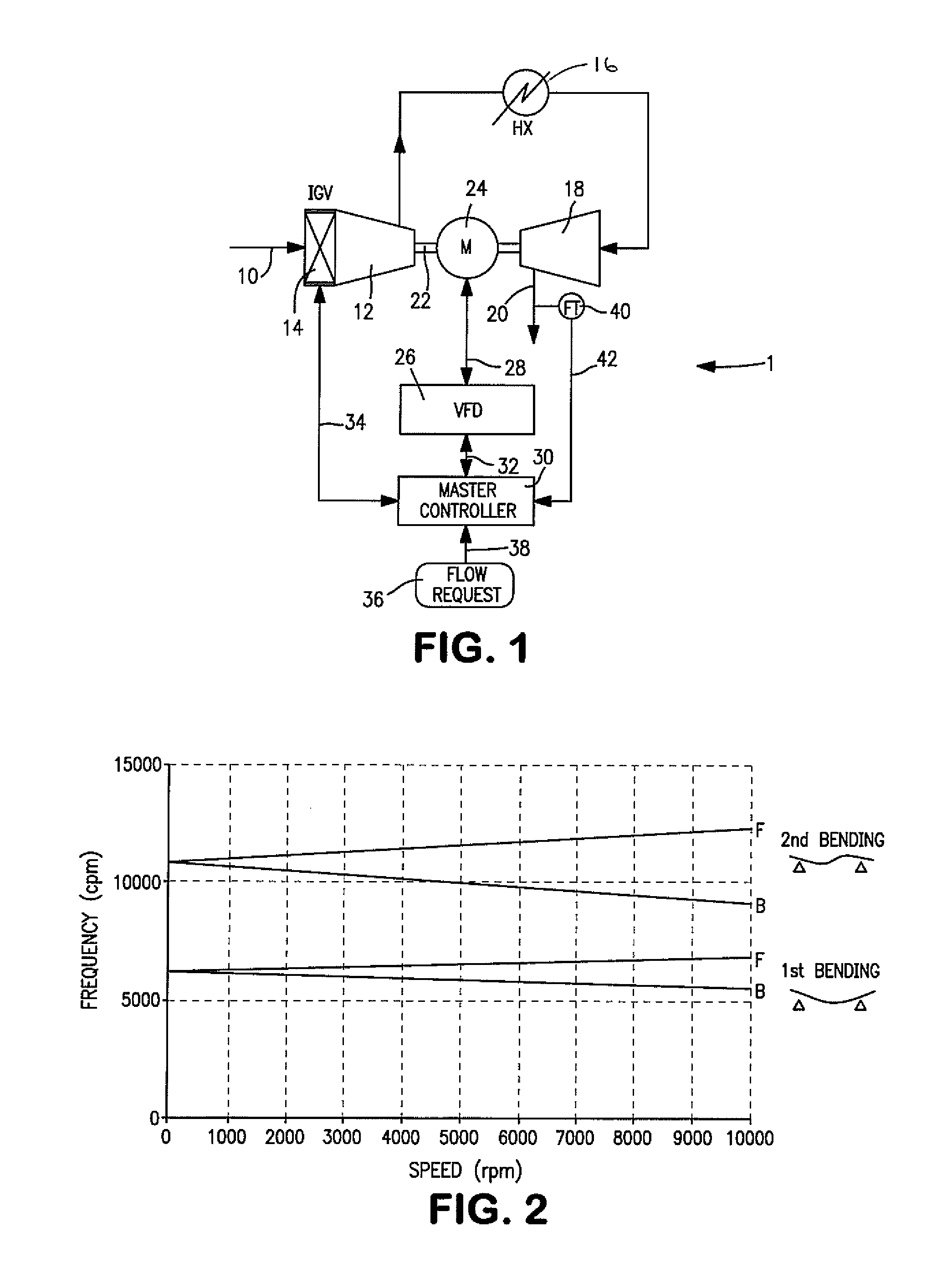
[0030]With reference to FIG. 1, a compression system 1 in accordance with the present invention is illustrated. Within compression system 1, a gas by way of a gaseous feed stream 10 is compressed in a first compressor 12 having inlet guide vanes 14 to adjust the flow rate of the gas to be compressed. First compressor 12 constitutes a first stage of compression. After removal of the heat of compression in an intercooler 16, the gas is further compressed in a second compressor 18 to a higher pressure to produce a compressed gas stream 20. First and second compressors 12 and 18 are centrifugal compressors of known design having an inlet, an impeller, a diffuser and a scroll-like volute to discharge the gas after having been compressed.

[0031]The first and second compressors 12 and 18 are connected to oppose ends of a motor shaft 22 of a motor 24 that drives the impellers of such compressors. Motor 24 can be a high speed permanent magnet motor. The speed of permanent magnet motor 24 is c...


PUM


Abstract

A method and apparatus for producing and controlling flow rate of a compressed gas produced by a compression system having one or more stages of compression formed by a centrifugal compressor or compressors, inlet guide vanes to control flow through the compression stage or stages and an electric motor directly coupled to the stage or stages having a restricted speed zone within which vibrational modes can damage the electric motor. A desired flow rate is obtained by speed adjustment alone and with the inlet guide vanes positioned at 0° when the speed will lie above or below the restricted speed zone. Where a desired flow rate would require extended operation of the electric motor at a speed within the restricted speed zone, the speed is set to the uppermost level of the restricted speed zone and the desired flow rate is obtained through appropriate positioning of the inlet guide vanes.

Description

FIELD OF THE INVENTION[0001]The present invention relates to a method and apparatus for producing a compressed gas and for controlling the flow rate of the compressed gas in which a compressor is directly coupled to an electric motor and a restricted speed zone exists where vibrational modes can damage the electric motor and / or the compressor. More particularly, the present invention relates to such a method and apparatus in which a desired flow rate is obtained by controlling the speed of the electric motor when such flow rate can be obtained by a speed that is not within the restricted speed zone and through inlet guide vane manipulation when such flow rate would otherwise be obtained by a speed within the restricted speed zone.BACKGROUND OF THE INVENTION[0002]Gases are typically compressed in compressors that are driven by electric motors. The compressors can be connected so that the gas is compressed in stages from ambient to a high delivery pressure. Interstage cooling is emplo...

Claims


Application Information

Patent Timeline
Patent Type & Authority Patents(United States)
IPC IPC(8): F04D27/02F04B49/20F04C28/14F04D29/66F04D29/46
CPCF04D27/0246F04B49/20F04C28/14F04D27/0261F04D27/0284F04D29/462F04D29/668F04B37/08F04B49/06F04B49/103F25J3/04018F25J3/04024F25J3/0409F25J3/04133F25J3/0429F25J3/04296F25J3/04303F25J3/04412F25J3/04678F25J3/04781F25J3/04884F25J3/04957F25J2230/20F25J2230/24F25J2230/40F25J2250/02Y02B30/70F04D17/122F04D25/06F04D27/004F04D27/0269F04D29/053F04D29/286F04D29/464
Inventor STANKO, MICHAEL J.ROYAL, JOHN H.ABDELWAHAB, AHMED F.SCHWARZ, CARL L.
Owner PRAXAIR TECH INC
Why Eureka
Try Eureka