

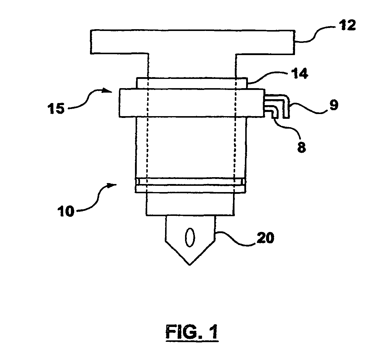
Electrical connector assembly for an arcuate surface in a high temperature environment and an associated method of use
a technology of electrical connectors and arcuates, applied in the direction of ohmic-resistance heating, heater elements, coupling device connections, etc., can solve the problems of time-consuming, expensive and time-consuming processing of specialized solder applications, and inability to reliably maintain the integrity of electrical connections so formed
- Summary
- Abstract
- Description
- Claims
- Application Information
AI Technical Summary
Problems solved by technology
Method used
Image

Examples
second embodiment
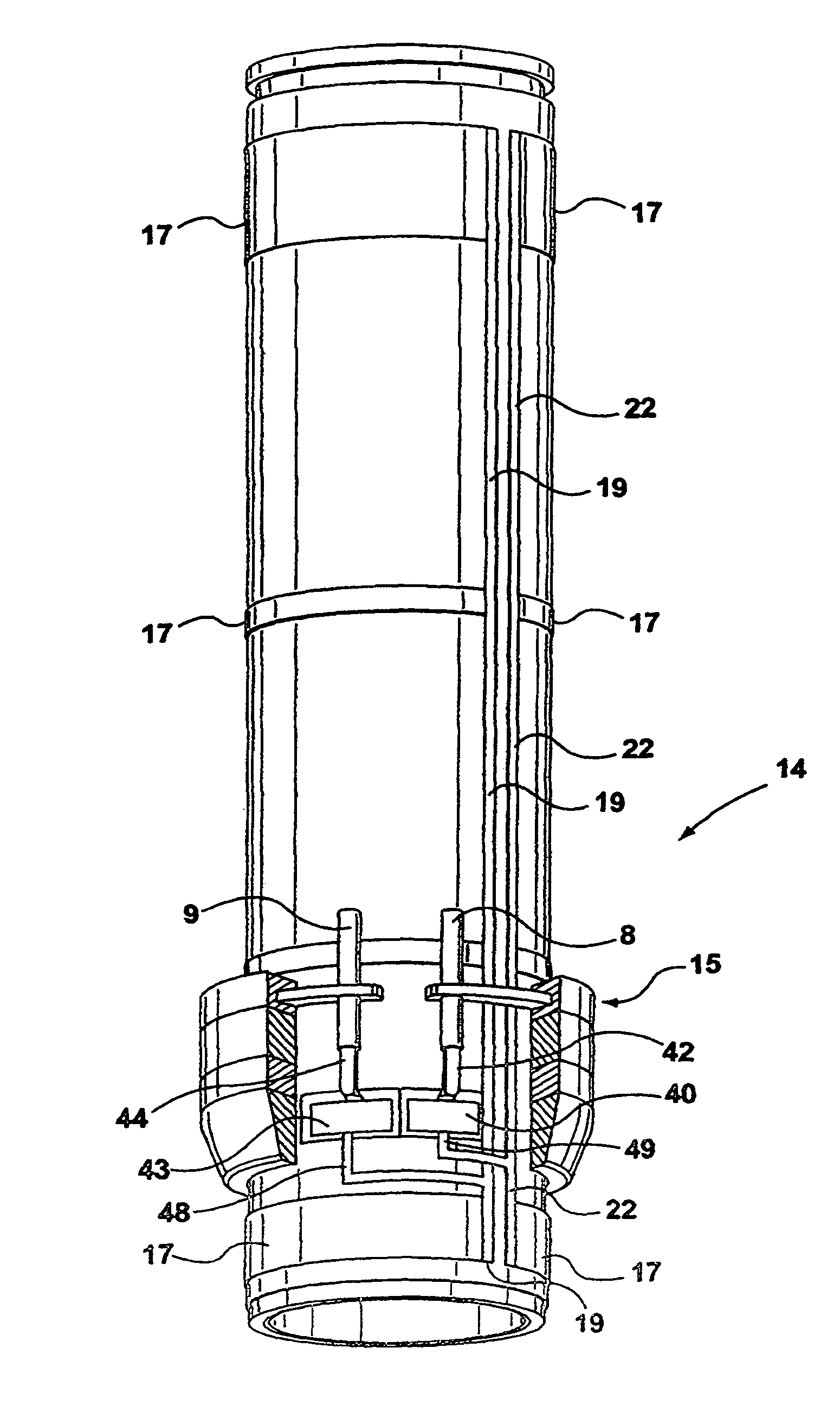
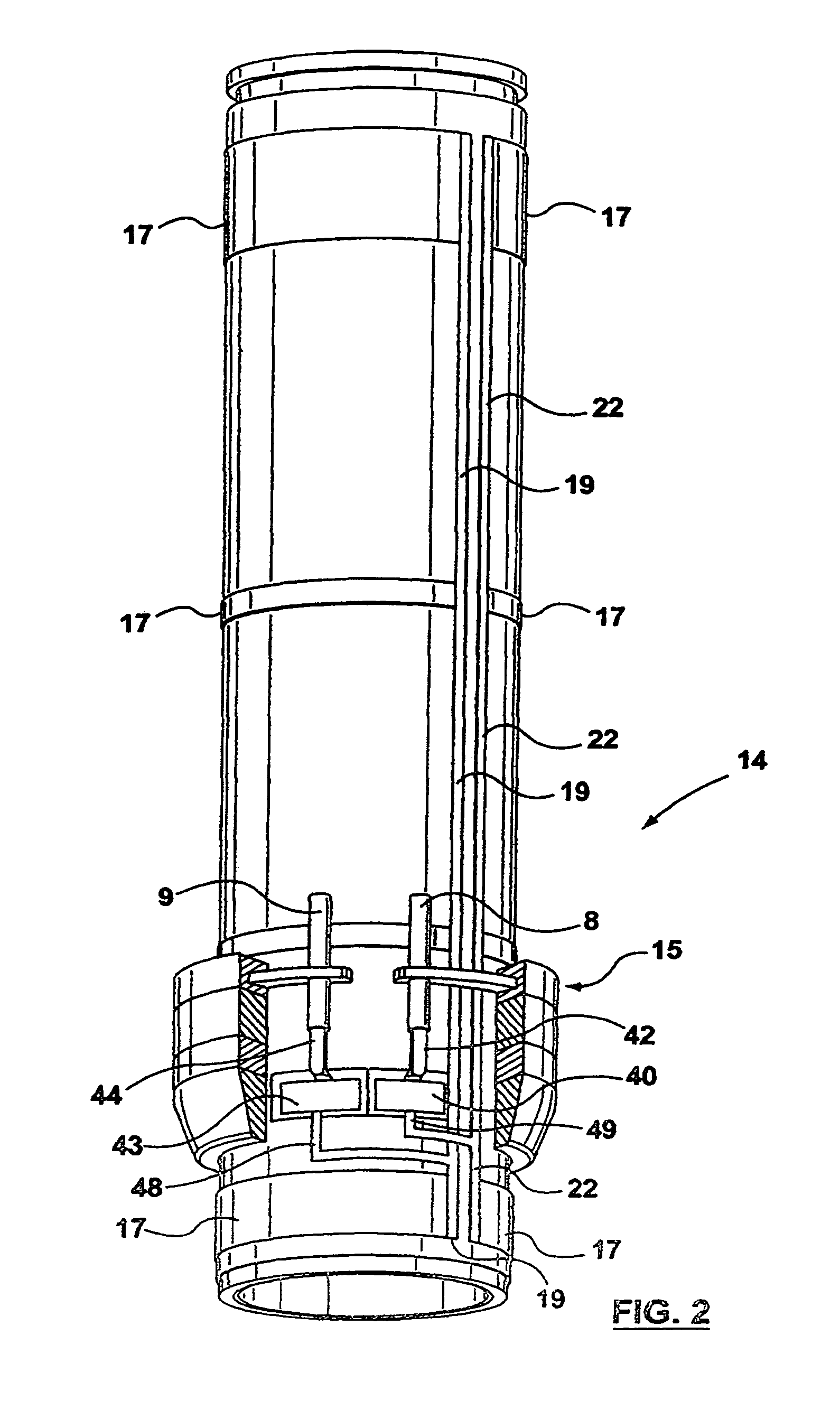
[0077]A second embodiment is shown in FIGS. 10 and 11, which illustrate an electrical connector that is generally indicated by numeral 50. A wide variety of interconnecting high temperature components can be utilized, which include a myriad of geometric structures or even a unitary structure can be utilized to form a housing. However, in this illustrative but nonlimiting example, there is an upper ring 54 positioned over a middle ring 56. The middle ring 56 is positioned over a lower ring 58. Positioned over the upper ring 54 is a ring top 52.
[0078]Referring now to FIG. 11, the electrical connector 50 is shown with the upper ring 54 and the middle ring 56 removed for clarity. The first electrical conductor 8 is electrically connected to a first contact assembly 60 that is attached to a first contact blade 62. The second electrical conductor 9 is electrically connected to a second contact assembly 64 that is attached to a second contact blade 66. This connection can be through spot w...
first embodiment
[0084]As previously explained with regard to the first embodiment, virtually any type of high temperature, electrical connector can supply electrical power to the first electrical conductor 8 and second electrical conductor 9 and be disconnected from the electrical power can operate as a disconnect mechanism to form an electrical conductor assembly.
[0085]Referring now to FIG. 15, an isolated view of the upper ring 54 is illustrated with a fifth indentation 94 for receiving the first contact assembly 60. There is a sixth indentation 96 for receiving the second contact assembly 64. There is an opening 92 for allowing passage of the first electrical conductor 8 and the second electrical conductor 9.
[0086]Referring now to FIG. 16, an isolated view of the ring top 52 is illustrated with the opening 92 for allowing passage of the first electrical conductor 8 and the second electrical conductor 9.
third embodiment
[0087]Referring now to FIG. 17, a third embodiment is generally indicated by numeral 100. An arcuate surface such as that provided by a cylindrical heater, as previously described, is indicated by numeral 14. There is a first electrical connector indicated by numeral 102 and a second electrical connector that is indicated by numeral 104. The cylindrical heater 14 can be a single heater, a heater with elongate nozzle housing and / or multiple two heaters joined together or linked in series. There is a first electrical power conductor 106 and a second electrical power conductor 108 that provide electrical power to the first electrical connector 102. There is an electrical jumper assembly 111 that provides electrical power to the second electrical connector 104 from the first electrical power conductor 106 and a second electrical power conductor 108.
[0088]Referring now to FIG. 18, the first electrical power conductor 106 is electrically connected to a first electrical conductor 110 that ...
PUM
| Property | Measurement | Unit |
|---|---|---|
| temperature | aaaaa | aaaaa |
| dielectric strength | aaaaa | aaaaa |
| dielectric strength | aaaaa | aaaaa |
Abstract
Description
Claims
Application Information