
Liquid crystal display and driving method thereof

a technology of liquid crystal display and driving method, which is applied in the field of demultiplexer for liquid crystal display, can solve problems such as the difficulty of normal driving of liquid crystal display, and achieve the effect of restoring the stress of switching devi

Active Publication Date: 2010-05-11
LG DISPLAY CO LTD
View PDF8 Cites 10 Cited by
  • Summary
  • Abstract
  • Description
  • Claims
  • Application Information

AI Technical Summary

Benefits of technology

The present invention is a liquid crystal display (LCD) and a method of driving it that aims to overcome the limitations and disadvantages of existing technology. The invention provides an LCD that minimizes variations in its characteristics and deterioration of its switching device. The method involves generating control signals with a first polarity of voltage to turn on the switching devices and a second polarity of voltage to restore the stress of the switching devices. The technical effects of the invention include improved performance and reliability of LCDs.

Problems solved by technology

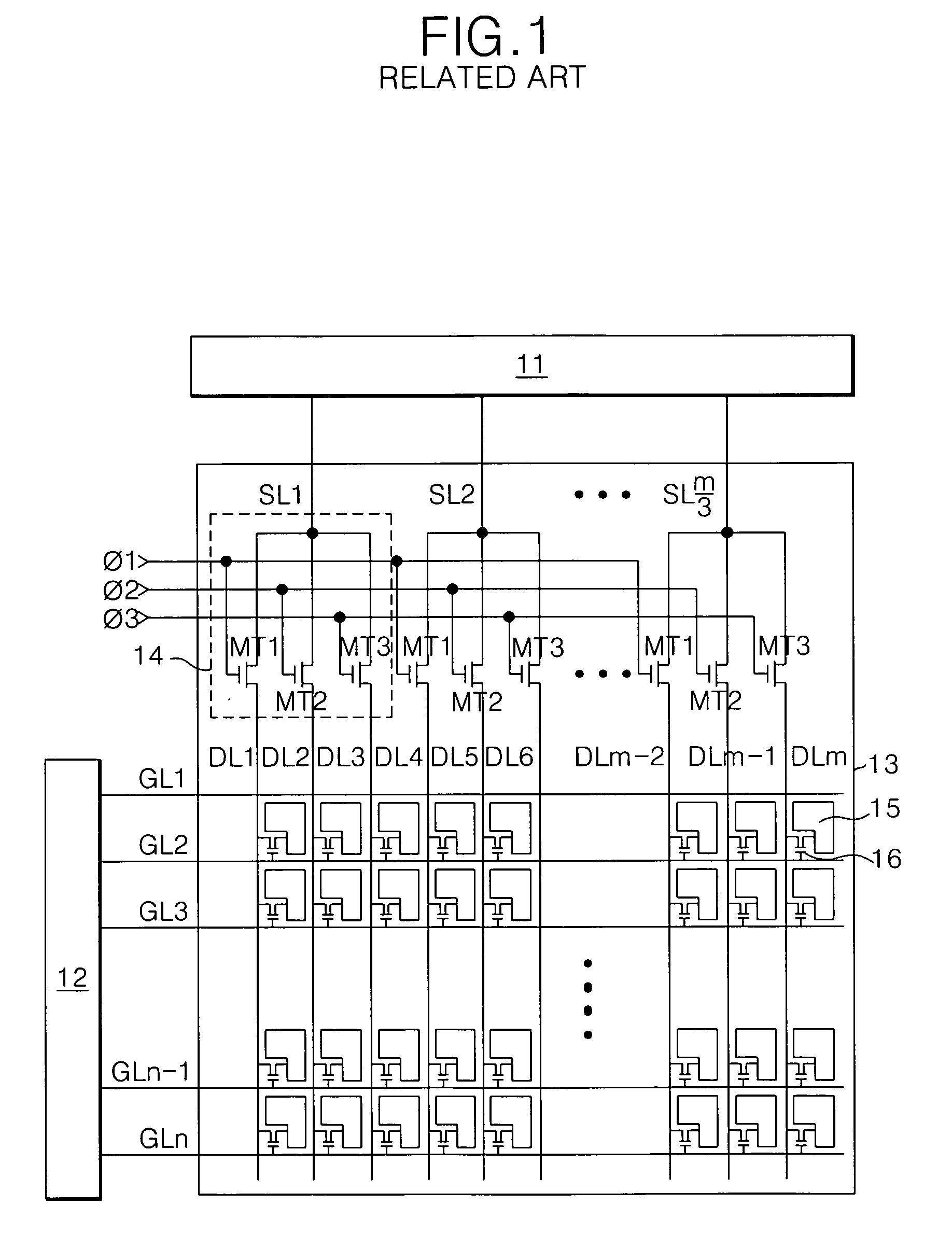
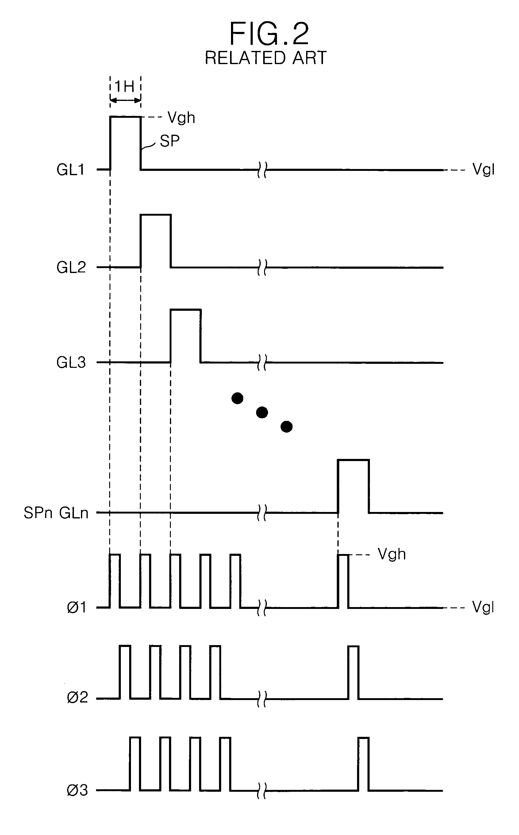
As the threshold voltage of the MUX TFT rises or falls in this manner, an operation of the demultiplexer 14 becomes unstable, thereby causing difficulty to normally drive the LCD.

Method used


Image

  • Liquid crystal display and driving method thereof
  • Liquid crystal display and driving method thereof
  • Liquid crystal display and driving method thereof

Examples


Embodiment Construction

[0036]Reference will now be made in detail to the preferred embodiments of the present invention, examples of which are illustrated in the accompanying drawings. Hereinafter, the preferred embodiments of the present invention will be described in detail with reference to FIGS. 6 to 13.

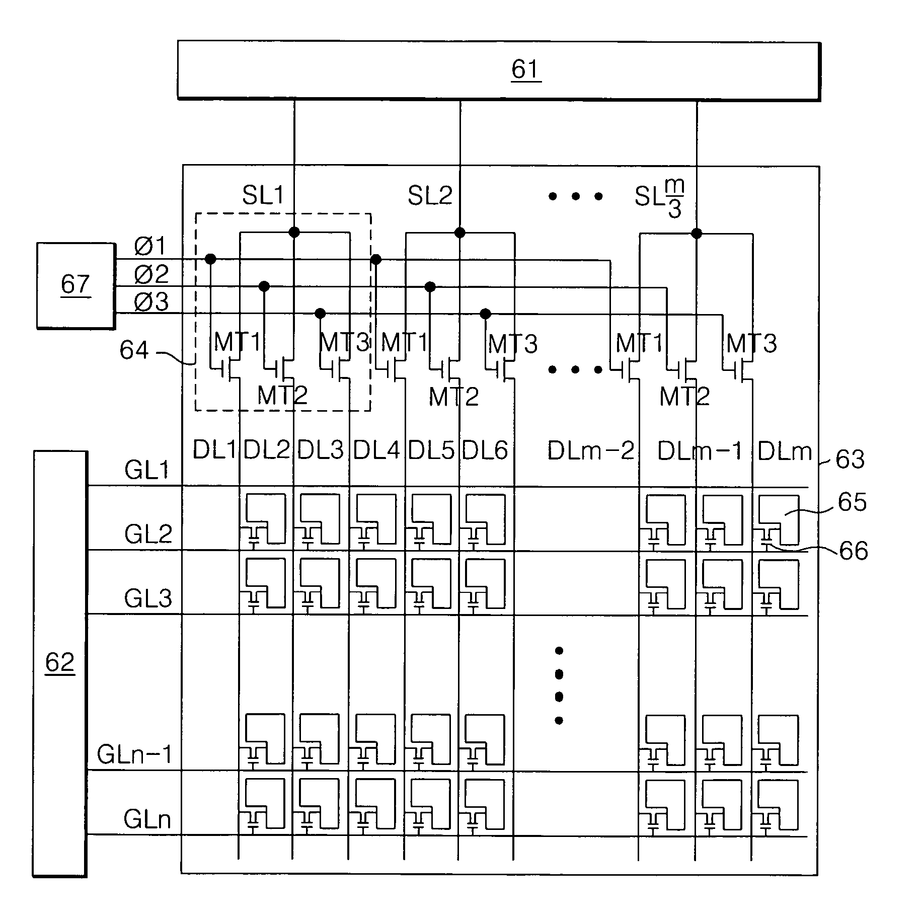
[0037]FIG. 6 schematically shows a liquid crystal display (LCD) according to an exemplary embodiment of the present invention. As shown in FIG. 6, the LCD includes an LCD panel 63 having m data lines DL1-DLm and n gate lines GL1-GLn crossing each other and a plurality of pixel driving TFTs 66 provided at crossing portions thereof, a demultiplexer 64 having MUX TFTs MT1, MT2 and MT3 provided between a data driving circuit 61 and the data lines DL1-DLm and implemented by a n-type amorphous silicon TFT, a control signal generator 67 for generating stress compensating control signals CΦ1, CΦ2 and CΦ3, and a gate driving circuit 62 for sequentially supplying scanning pulses to the gate lines GL1-GLn.

[0038]T...


PUM

PropertyMeasurementUnit
threshold voltageaaaaaaaaaa
voltageaaaaaaaaaa

Abstract

A liquid crystal display (LCD) device includes an LCD panel having a plurality of data lines and a plurality of gate lines crossing the data lines, a data driving circuit to generate a data voltage, a demultiplexer to apply the data voltage from the data driving circuit to the data lines using a plurality of switching devices, and a control signal generator to generate a plurality of control signals having a first polarity of voltage in order to turn on the switching devices and in order to add a second polarity of voltage to the control signals.

Description

[0001]This application claims the benefit of Korean Patent Application No. P2003-92693 filed in Korea on Dec. 17, 2003, which is hereby incorporated by reference.BACKGROUND OF THE INVENTION[0002]1. Field of the Invention[0003]The present invention relates to a liquid crystal display (LCD), and more particularly, to a demultiplexer for an LCD and a driving method thereof.[0004]2. Discussion of the Related Art[0005]In general, an LCD controls light transmittance of liquid crystals in accordance with a video signal so that a picture corresponding to the video signal can be displayed on the LCD. The LCD includes an LCD panel having liquid crystal cells arranged in an active matrix type, and driving circuits for driving the LCD panel. In the LCD panel, a plurality of data lines and a plurality of gate lines are intersected, and pixel driving thin film transistors (TFTs) are provided at respective intersected portions. The driving circuits of the LCD include a data driving circuit for sup...

Claims


Application Information

Patent Timeline
Patent Type & Authority Patents(United States)
IPC IPC(8): G09G3/36G02F1/133G09G3/20H04N5/66
CPCG09G3/3688G09G2310/0297G02F1/133
Inventor JANG, YONG HOYOON, SOO YOUNG
Owner LG DISPLAY CO LTD
Learn More