Moving mechanism for cruiser arch

Inactive Publication Date: 2010-05-18
TEVLIN TIMOTHY J
View PDF9 Cites 0 Cited by
  • Summary
  • Abstract
  • Description
  • Claims
  • Application Information

AI Technical Summary

Benefits of technology

[0012]The predetermined distance, over which only linear, non-rotational carriage travel can occur, is selected to provide for initial pivoting but need not be sufficient to allow complete arch pivoting to the lowered position. The predetermined distance, plus the additional linear travel that coincides with carriage rotation after the leading coupling element enters the second track section, is sufficient to allow the complete tilting of the arch assembly leg. If desired, the guide track and spacing between the coupling elements can be configured to provide a linear, non-rotational extension that completely clears the leg or tilting to the lowered position.
[0013]In any event, the initial non-rotational linear travel avoids the need to locate the leg/hull pivotal connection between the leg and hull outside of the leg and hull, for example as shown in the aforementioned Sparkes patent. The pivotal connection c

Problems solved by technology

Stowage can be more difficult, and more expensive in facilities that charge by the cubic foot.
While arch assemblies can be mounted in a manner that allows their detachment for the hull when the cruiser encounters a bridge or other overhead obstruction, detachment and reattachment are difficult in view of the weight and bulk of the arch assembly.
This still calls for manual handling, which can be difficult in view of the larger size and weight of arch assemblies as co

Method used


Image

  • Moving mechanism for cruiser arch
  • Moving mechanism for cruiser arch
  • Moving mechanism for cruiser arch

Examples


Example

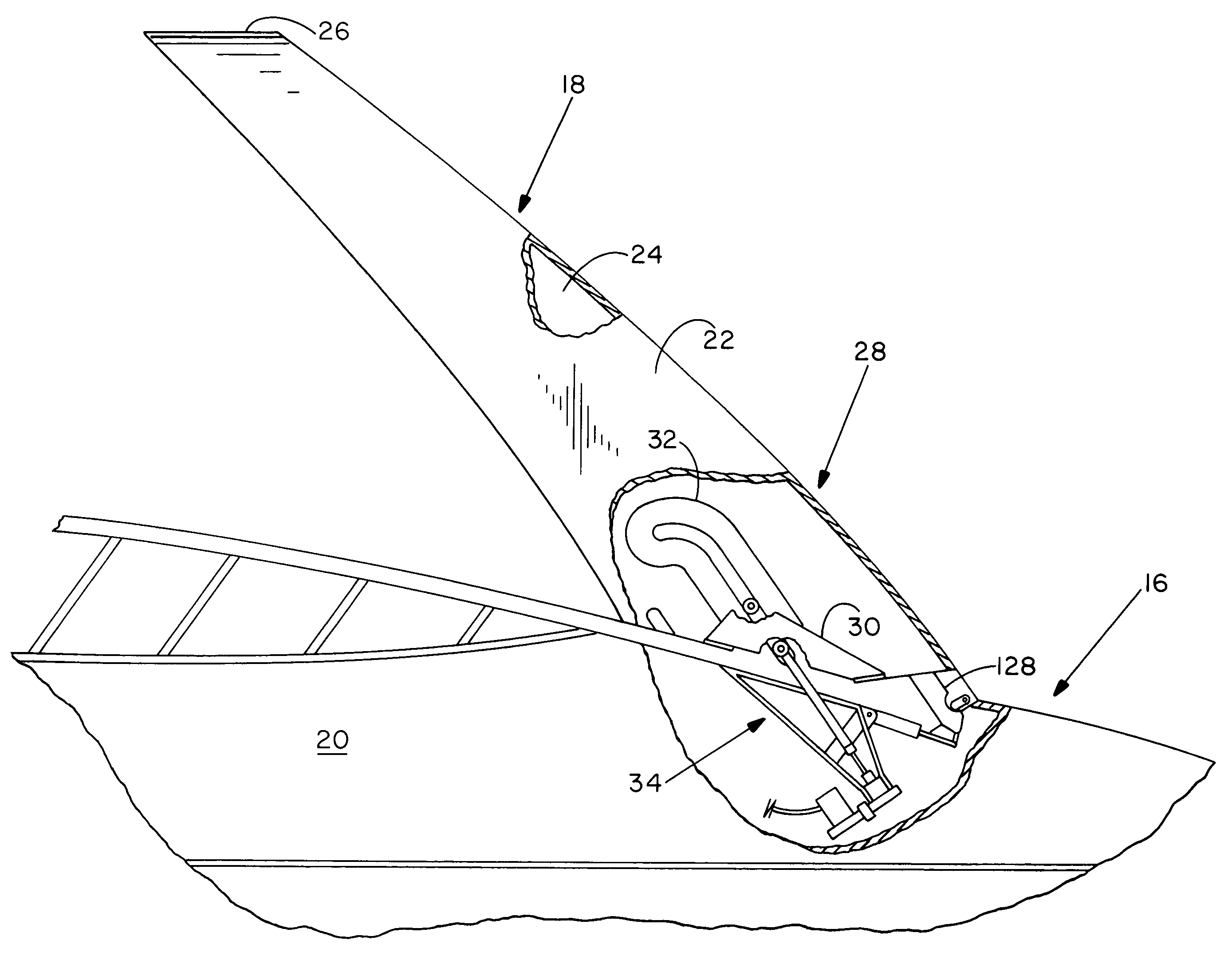
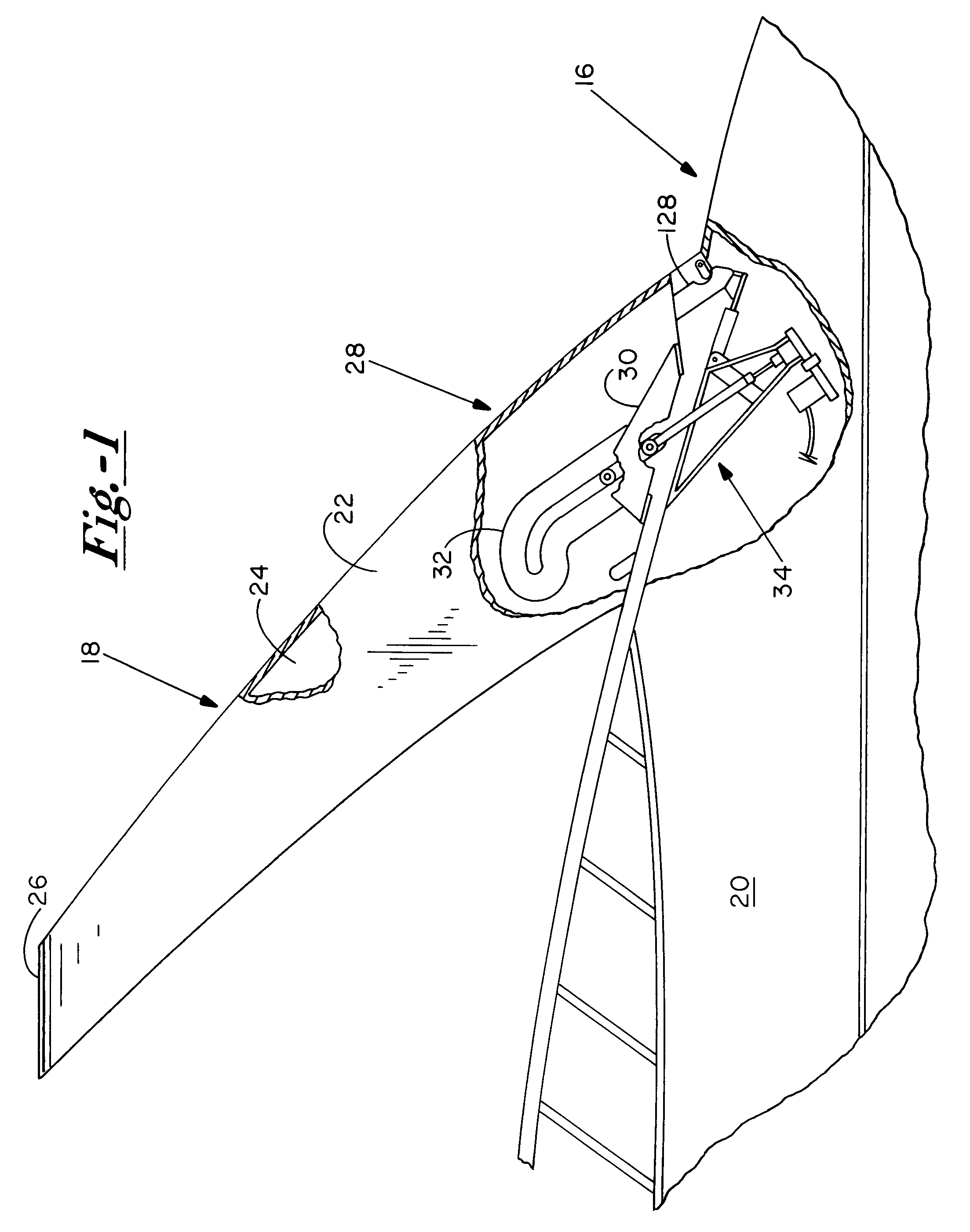
[0041]Turning now to the drawings, there is shown FIG. 1 a cruiser 16 and a cruiser arch 18 mounted movable to a hull 20 of the cruiser between a working position as shown, and a clearance position (FIG. 12) in which the arch is lowered to provide improved overhead clearance. In the working position, arch 18 supports radar antennas, radio antennas, and other electrical equipment (not shown) for normal use.

[0042]Arch 18 includes opposite legs 22 and 24 that are generally upright in the working position, although somewhat forwardly inclined. The opposite legs are joined by a horizontal transom or cross member 26.

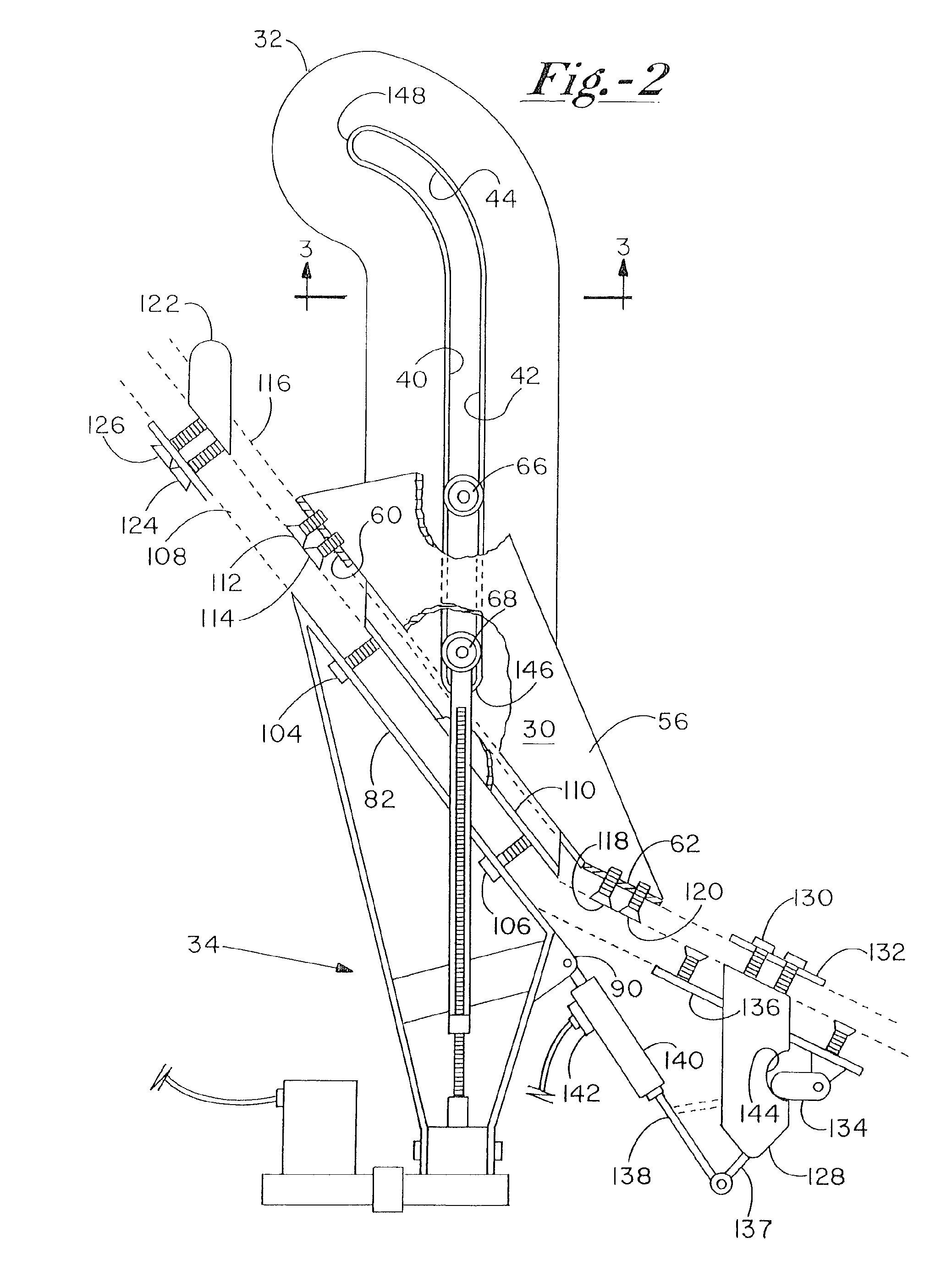
[0043]Portions of leg 22 and hull 20 near the gunwale are broken away to reveal an arch moving and controlling mechanism 28. Mechanism 28 is housed within recesses formed in leg 22 and hull 20, and thus is concealed from view when arch 18 is in the working position. The major components of mechanism 28 include a carriage 30 integrally mounted to leg 22, a carriage guide 32 mou...


PUM


Abstract

A cruiser arch moving and control mechanism includes a pair of carriage guides (32, 150, 188) fixed to opposite sides of a cruiser hull, and a pair of carriages (30, 170), each mounted to one of the opposing legs of the cruiser arch. Each of the carriage guides includes a slot (40, 156, 190) with an elongate linear track section and an adjacent arcuate track section. Each carriage includes a pair of spaced apart bearings (76/78, 164/176, 198/200) that are confined for reciprocal travel along one of the slots to support the carriage moveably relative to the associated carriage guide. Two linear actuators (34), one coupled between each carriage and its associated guide, are extendable and retractable in concert to move the arch between working and clearance positions. The carriage guides are configured to prevent any substantial rotation of the carriages until the arch is extended linearly at least a predetermined distance from the working position.

Description

BACKGROUND OF THE INVENTION[0001]The present invention relates to arch or bridge assemblies used in cruisers and other watercraft for supporting radar antennas and other equipment, and more particularly to mechanisms for controlling movement of such assemblies between a generally upright position for use, and a lowered position for stowage, on-land transit or for allowing the watercraft to pass under bridges and other obstructions having low clearance.[0002]For years, cabin cruisers and other watercraft have employed arch-shaped structures for supporting radar antennas, radio antennas and other electronic equipment above the normal deck level. A typical arch assembly includes an opposed pair of generally upright legs secured to the gunwales or elsewhere on opposite sides of the hull, and a transverse bridge member or transom attached to the tops of the legs and spanning the distance between them. Typically, the equipment is mounted to the bridge member.[0003]While effective in suppo...

Claims


Application Information

Patent Timeline
IPC IPC(8): B63B15/00B63B17/00
CPCB63B15/00Y10T74/20232B63B2015/0025B63B2015/005
Inventor TEVLIN, TIMOTHY J.
Owner TEVLIN TIMOTHY J
Why Eureka
Try Eureka