Electrically trimmable resistor device and trimming method thereof

Active Publication Date: 2013-12-26
STMICROELECTRONICS INT NV
View PDF6 Cites 3 Cited by
  • Summary
  • Abstract
  • Description
  • Claims
  • Application Information

AI Technical Summary

Benefits of technology

[0019]This solution avoids the need to apply a potential difference across the two terminals of the functional resistor, but, in fact, enables heating only of a small portion of the functional resistor. I

Problems solved by technology

As is known, in many integrated circuits, some quantities of the integrated circuit are modified since, at the end of the manufacturing processes and because of the tolerances of its components, the function of the integrated electronic device is impaired or other than optimal.
Even though some circuit configurations enable more or less effective compensation of temperature and input voltage changes, the final integrated circuit is unlikely to present, at the end of the production cycle, the desired voltage value.
However, since the device is provided with a window transparent to laser light, it is problematical to apply the technique to devices closed within a package, since the latter, in general, is opaque to radiation.
In addition, the costs for purchase and use of a machine dedicated to laser trimming may be rather high, and the trimming process may be time intensive.
Frequently, these techniques employ operations that may be electrically performed using appro

Method used


Image

  • Electrically trimmable resistor device and trimming method thereof
  • Electrically trimmable resistor device and trimming method thereof
  • Electrically trimmable resistor device and trimming method thereof

Examples


Example

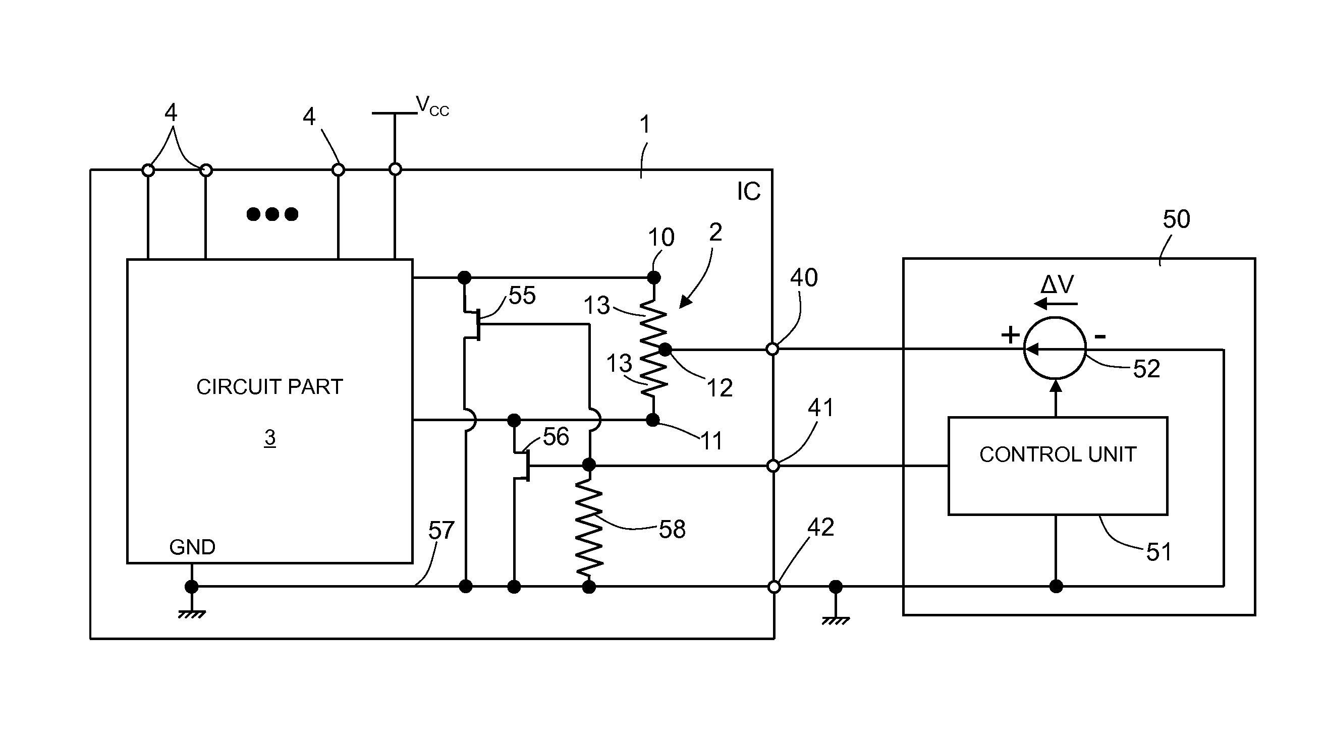
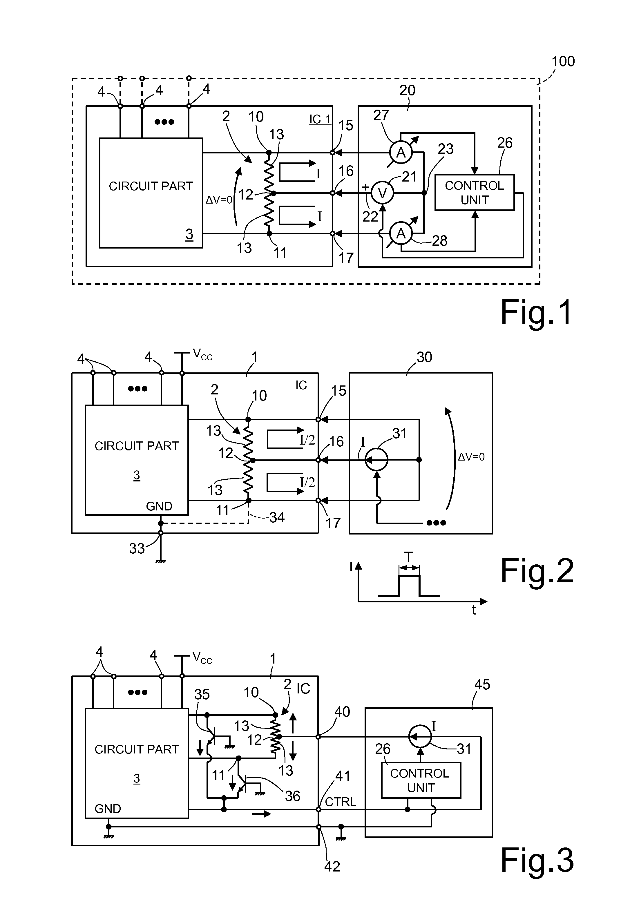
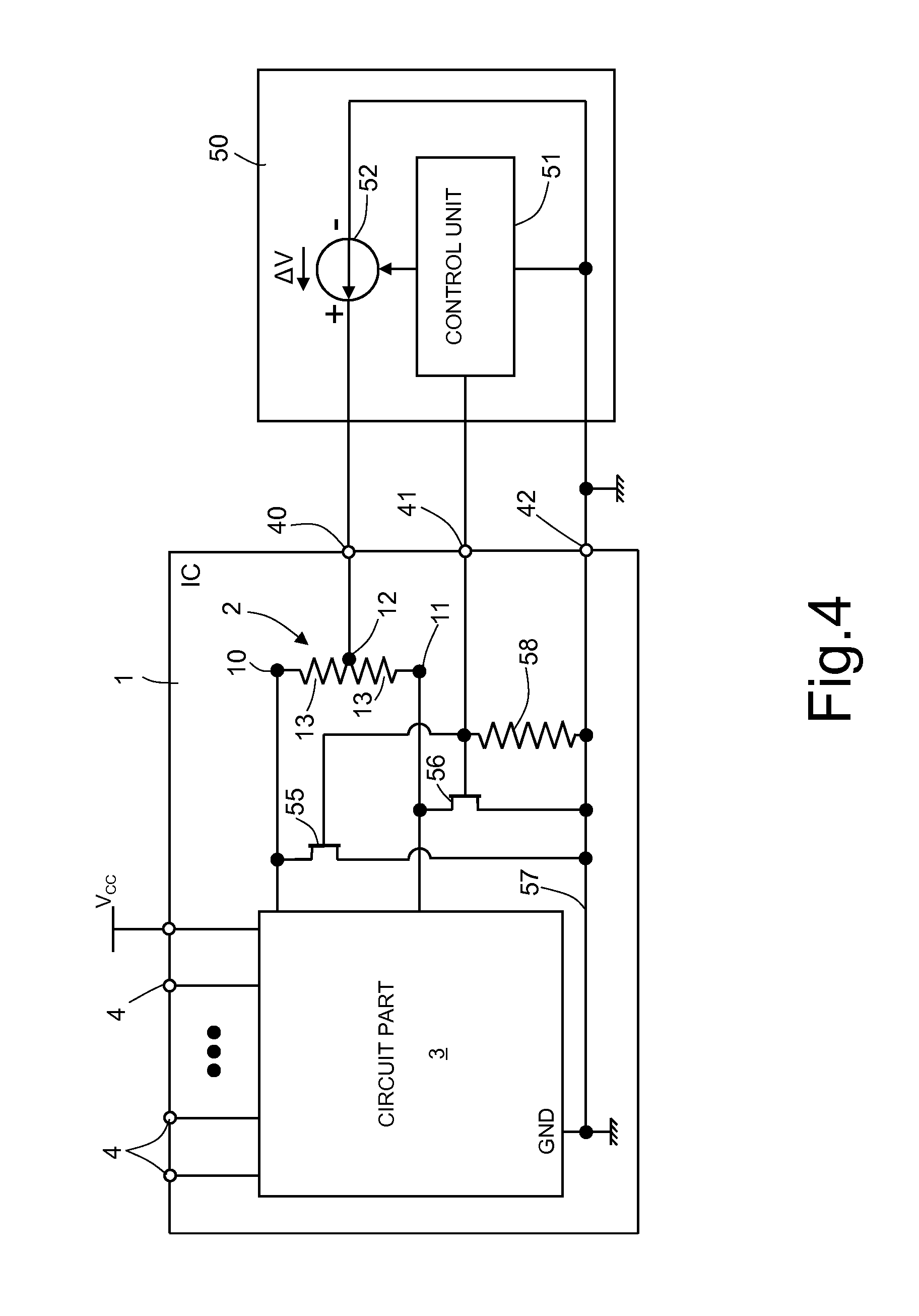
[0031]Referring to the prior art solution discussed above, in which the material of a resistor is heated by applying an electrical current pulse to the resistor so that it heats by Joule effect, one of the major drawbacks of this solution lies in that, to cause a current to circulate within the resistor, a potential difference is applied across the latter. The resistor forms part, however, of an integrated circuit, i.e., of a circuit including a plurality of active and passive components that may be arranged in any of a very large number of circuit configurations, according to the application. In general, it is difficult to foresee whether the potential difference necessary for resistor trimming may induce current elsewhere in the circuit that causes permanent damage to the circuit, which may limit the possibilities of this solution. FIG. 1 shows an integrated circuit 1 including a trimmable resistor 2 and a circuit part 3. The integrated circuit 1 may be of any kind, of an analog o...


PUM


Abstract

An integrated circuit has a circuit part and a trimmable resistor, the resistance whereof may be modified by Joule effect. The trimmable resistor has first and second connection terminals coupled to the circuit part, and an intermediate terminal that divides the trimmable resistor into two portions. The first and the second connection terminals and the intermediate terminal are coupled to respective pads configured to receive electrical quantities designed to cause, in use, a respective trimming current flow in each portion. In this way, a substantially zero voltage drop is maintained between the first and second connection terminals while current is flowing in the resistor to change an electrical characteristic of the resistor, such as resistance or thermal coefficient.

Description

BACKGROUND[0001]1. Technical Field[0002]The present disclosure relates to an electrically trimmable resistor device and to the trimming method thereof.[0003]2. Description of the Related Art[0004]As is known, in many integrated circuits, some quantities of the integrated circuit are modified since, at the end of the manufacturing processes and because of the tolerances of its components, the function of the integrated electronic device is impaired or other than optimal. Such modifications are, for example, particularly beneficial in applications that employ a high precision in the performed functions.[0005]For example, the need for precise regulation of biasing quantities is particularly felt in devices generating high-precision reference voltages that use supply voltages variable within a rather wide range of values.[0006]This type of devices is used to generate, starting from the variable supply voltage, a voltage that is very precise and stable over time and that is largely unaff...

Claims


Application Information

Patent Timeline
IPC IPC(8): H01C10/50
CPCH01C10/50H01C17/232H01C17/265H01L22/14H01L28/20H01L23/5228H01L22/20H01L2924/0002H01L2924/00
Inventor SANTANGELO, ANTONELLOPRIVITERA, STEFANIA MARIA SERENA
Owner STMICROELECTRONICS INT NV
Why Eureka
Try Eureka