Printing system

Active Publication Date: 2011-12-22
RISO KAGAKU CORP
View PDF7 Cites 1 Cited by
  • Summary
  • Abstract
  • Description
  • Claims
  • Application Information

AI Technical Summary

Benefits of technology

[0011]However, in the above technique, since data on measured transfer speeds of the transfer belt includes fractions attributable to roller eccentricity, the average travel speed calculated from such measurement data also includes a fraction attributable to roller eccentricity. Such the average travel speed constitutes a basis for calculations to determine a set of speed ratios, so the belt profile data may not be sufficiently correct. As a result, the belt profile data may not be correct enough to exhibit due effects to suppress shot deviations.
[0012]The present invention has been devised in view of such issues. It is an object of the present invention to provide a printing system adapted to suppress shot deviations due to irregularities in thickness of a transfer belt and/or eccentricity of rollers over which the transfer belt is stretched.
[0013]To achieve the object described, according to an aspect of the present invention, there is a printing system comprising a set of rollers, a transfer belt driven by the set of rollers to transfer a sheet; an ink head configured to propel droplets of ink onto the sheet put on the transfer belt; a measuring element configured to measure travel distances or travel speeds of the transfer belt at a prescribed measuring spot and at intervals with a prescribed rotation angle of one of the set of rollers, as a set for one or more go-around revolutions of the transfer belt at a prescribed measuring spot; a roller profile calculator configured to calculate a roller profile data as a set of fractions attributable to an eccentricity of the set of rollers in a set of measurement data obtained at the measuring element; a belt profile calculator configured to remove the set of fractions attributable to the eccentricity from the set of measurement data, and calculate a belt profile data representative of irregularities in thickness of the transfer belt based on the set of measurement data after removal of the set of fractions attributable to the eccentricity; and a discharge controller configured to control timing for discharge of ink to the sheet at the ink head based on the belt profile data and the roller profile data, wherein the belt profile calculator calculates a set of eccentricity-removed average data representative of travel distances or travel speeds of the transfer belt at t

Problems solved by technology

Such the average travel speed constitutes a basis for calculations to determine a set of speed ratios, so the belt profile data may not

Method used


Image

  • Printing system
  • Printing system
  • Printing system

Examples


Example

First Embodiment

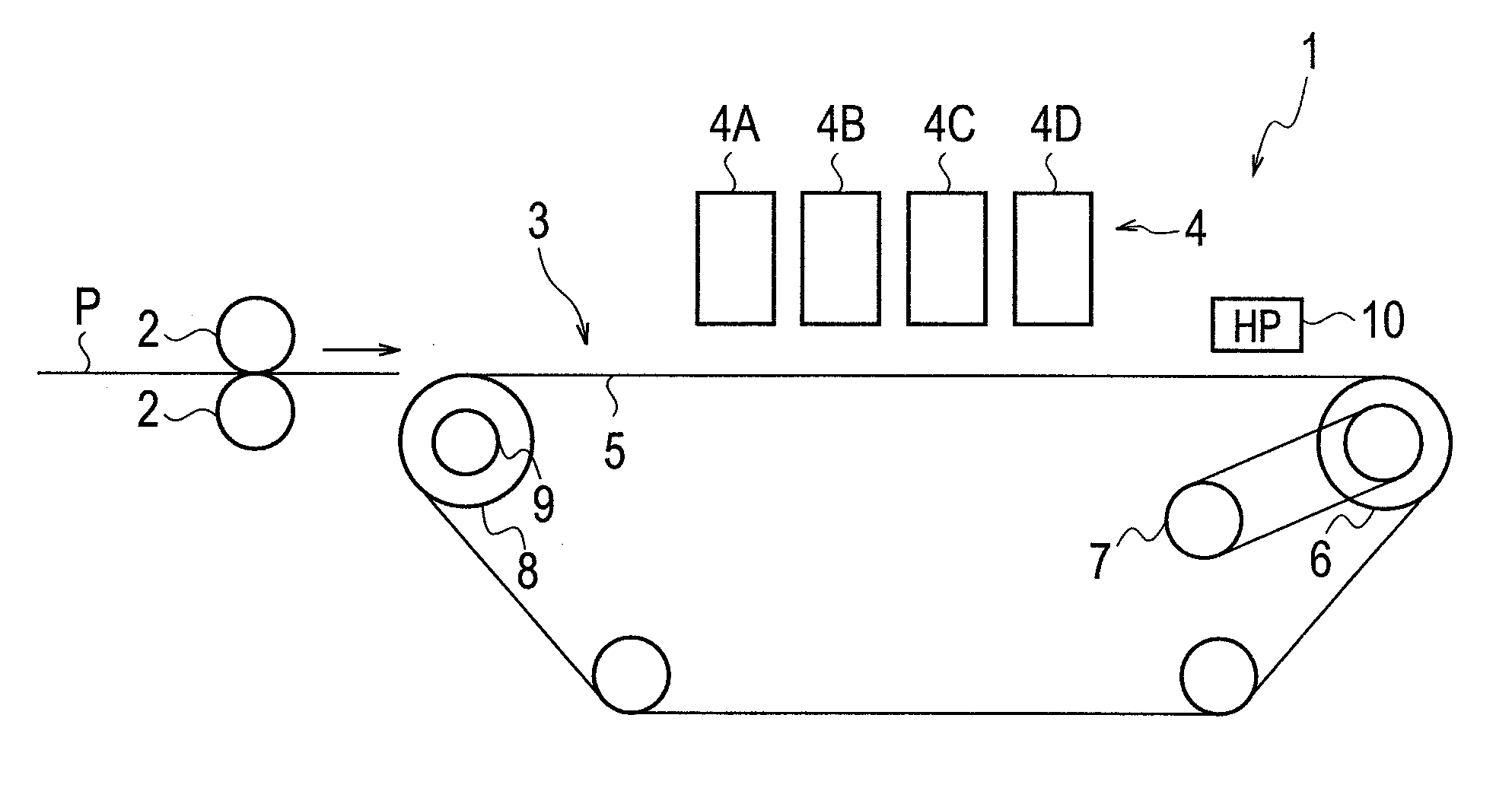
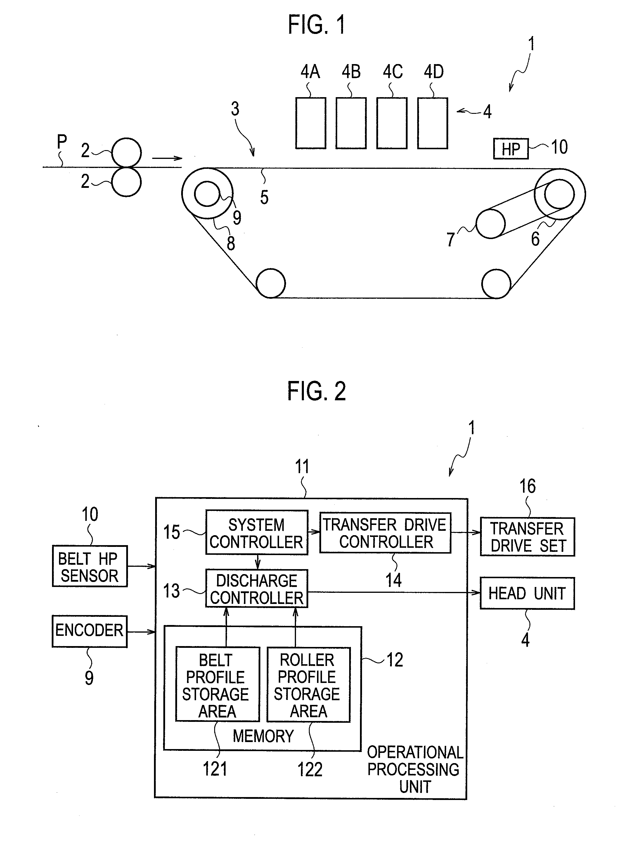
[0035]FIG. 1 is a diagram of schematic configuration of a printing machine constituting a printing system according to a first embodiment As shown in FIG. 1, according to the first embodiment, there is a printing machine 1 including a set of register rollers 2, a sheet transfer section 3, and a head unit 4.

[0036]The set of register rollers 2 is configured to reset a print sheet P, which has been picked up from a sheet feeder rack (non-depicted) and fed in a position, in a corrected position to avoid oblique transfer, and to send out to the transfer section 3 at a prescribed timing.

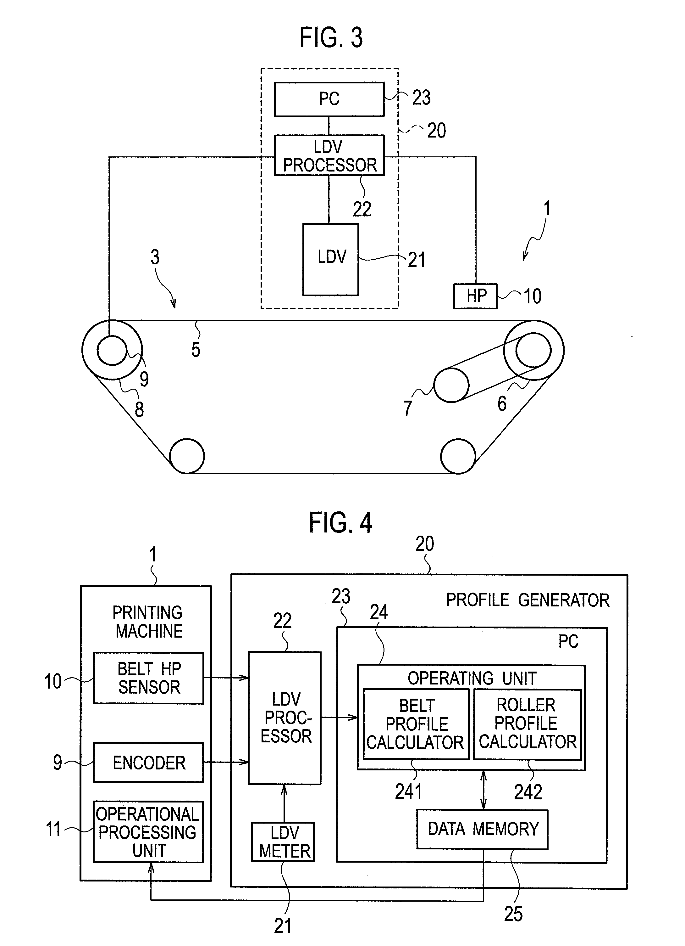
[0037]The transfer section 3 has a transfer belt 5 to be driven to go around with a top side facing the head unit 4, and includes a drive roller 6 for driving the transfer belt 5. The transfer section 3 includes: a drive motor 7 for driving the drive roller 6; and a driven roller 8 to be driven from the drive roller 6 through the transfer belt 5. The transfer section 3 further includes: an ...

Example

[0087]Namely, the comparative example is different from the first embodiment in order of the step of removing fractions attributable to the eccentricity of driven roller 8. The first embodiment has a sequence of sets of measurement data deprived of eccentricity-attributable fractions, for use to determine a mean travel distance, while the comparative example calculates a mean travel distance with eccentricity-attributable fractions inclusive.

[0088]FIG. 10 is a graph showing sets of differences of measurement data to a mean travel distance in the comparative example, and FIG. 11, a graph showing examples of sets of differences of measurement data to a mean travel distance in the first embodiment. In FIG. 10, as well as in FIG. 11, there are plotted sets of difference values for two go-around revolutions of the transfer belt 5, and a set of averaged difference values in between. It is noted that the set of averaged difference values in FIG. 11 corresponds to the second set of deviatio...

Example

Second Embodiment

[0115]Description is now made of a printing system according to a second embodiment, which is different from the printing system according to the first embodiment, in that it has a printing machine 1 including one or more cameras additionally provided to take frames of local images at prescribed timings of a dedicated chart on any of a prescribed number of test sheets (e.g. two sheets of a dedicated chart 41 for size A3 in FIG. 17) exceeding a whole circumference of a transfer belt 5, as the belt 5 moves carrying the sheets.

[0116]Any camera is mounted in position so that any image frame taken has its center on a straight line preset as a reference for alignment of any line of nozzles at any ink head of a head unit 4. This embodiment includes a camera 40 mounted on an ink head 4A.

[0117]FIG. 15 is a plan view showing the camera 40 mounted on the ink head 4A. As illustrated in FIG. 15, the ink head 4A includes two sets of three unit heads 4A1, 4A3, 4A5 and 4A2, 4A4, 4A...


PUM


Abstract

An LDV meter 21 cooperates with an LDV processor 22 to measure travel distances or travel speeds of a transfer belt at a prescribed measuring spot and at intervals with a prescribed rotation angle of one of a set of rollers, on which the transfer belt is stretched, as a set for one or more go-around revolutions of the transfer belt. A roller profile calculator 242 calculates a roller profile data as a set of fractions attributable to an eccentricity of the set of rollers in a set of measurement data. A belt profile calculator 241 removes the set of fractions attributable to the eccentricity from the set of measurement data and calculates a belt profile data representative of irregularities in thickness of the transfer belt based on the set of measurement data after removal of the set of fractions attributable to the eccentricity. In printing, a printing machine 1 controls timing for discharge of ink at an ink head based on the belt profile data and the roller profile data.

Description

BACKGROUND OF THE INVENTION[0001]1. Field of the Invention[0002]The present invention relates to a printing system including a printing machine using a transfer belt for transferring a sheet to make a print thereon.[0003]2. Description of Related Art[0004]There have been known printing systems including a printing machine adapted to transfer a sheet as a print medium held on a transfer belt and to make a print thereon by propelling droplets of ink from an ink head onto the sheet.[0005]When such a printing system is put in a printing service, the transfer belt is driven in a controlled manner for a constant travel speed. However, the travel speed of the transfer belt may change by so-called irregularities in thickness of the transfer belt in addition to similar affection by eccentricity of rollers over which the belt is stretched.[0006]The transfer belt may thus travel at non-constant speeds causing droplets of ink propelled out of the ink head to be shot in positions deviated from d...

Claims


Application Information

Patent Timeline
IPC IPC(8): B41J29/38
CPCB41J29/38B41J11/007
Inventor KUBOTA, MUTSUMINISHIHATA, MASAHIRO
Owner RISO KAGAKU CORP
Why Eureka
Try Eureka