Fabric sweeper

a technology of fabric sweeper and vacuum head, which is applied in the direction of carpet sweeper, carpet cleaner, cleaning equipment, etc., can solve the problems of large mechanical cleaning device, inconvenient use, and high inefficiency in removing dirt from the device, so as to facilitate the removal of dust, dirt and other debris

Active Publication Date: 2010-05-25
SC JOHNSON & SON INC
View PDF46 Cites 19 Cited by
  • Summary
  • Abstract
  • Description
  • Claims
  • Application Information

AI Technical Summary

Benefits of technology

[0006]According to a primary aspect of the present invention, a fabric cleaning and / or sweeping device is provided within a housing that includes a pair of movable fabric cleaning members. The cleaning members are secured within a recess in the housing such that each member is engageable with the fabric to be cleaned and with the opposed fabric cleaning member. The movable cleaning members rotate with respect to the housing as the cleaning device is moved over the fabric surface, and pick up any dust, dirt or other debris on the fabric surface. The movable cleaning members are secured within the housing in a manner which enables the members to rotate independently of one another, but also that the cleaning members selectively come into contact with one another. When the cleaning members contact one another, the members effectively act as a cleaning mechanism for one another, urging the dust, dirt and other debris off of the opposite member and into a collection chamber for the device. The members can easily pick up dust, dirt and other debris from the fabric surface due to the construction of the cleaning members which include an outer surface formed of a material that readily attracts pet hair, crumbs, dust, lint, allergens and other materials present on the fabric surface. The materials are also chosen to be somewhat flexible such that the material, in addition to being cleaned by the material positioned on the opposed rotatable member, can be further cleaned of the dirt, dust and other debris picked up by the material as a result of the contact of the material on each cleaning member with the housing.
[0008]According to still another aspect of the present invention, the housing within which the cleaning members and the collection chamber are positioned is designed to enable easy handling and use by an individual to clean a fabric surface. Additionally, the housing is formed with a minimum of parts which can each be formed of lightweight materials that are relatively low cost and easy to manufacture into the housing components.

Problems solved by technology

However, due to the often large and cumbersome construction of these types of mechanical vacuum fabric cleaning devices, these devices are often not suitable for use in certain situations where the fabric surface to be cleaned is relatively small, or is positioned in a difficult to access location.
In addition, for various instances of spot cleaning certain fabric surfaces, a large mechanical cleaning device is often impractical for the particular cleaning task.
Furthermore, for that component of the dirt, dust and other debris that is actually contained within the housing as a result of the proper operation of the device, the debris must be dispensed by inverting the device and shaking the housing such that the debris moves through an opening in the housing, which is a highly inefficient manner to remove the dirt from the device.

Method used


Image

  • Fabric sweeper
  • Fabric sweeper
  • Fabric sweeper

Examples


Embodiment Construction

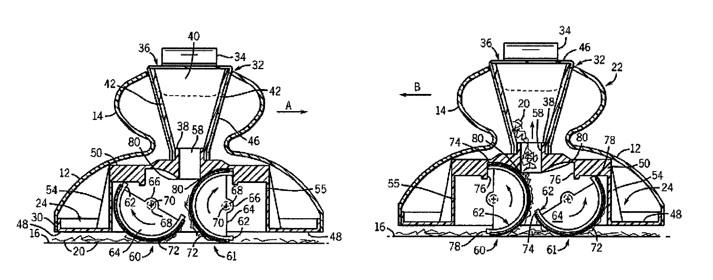
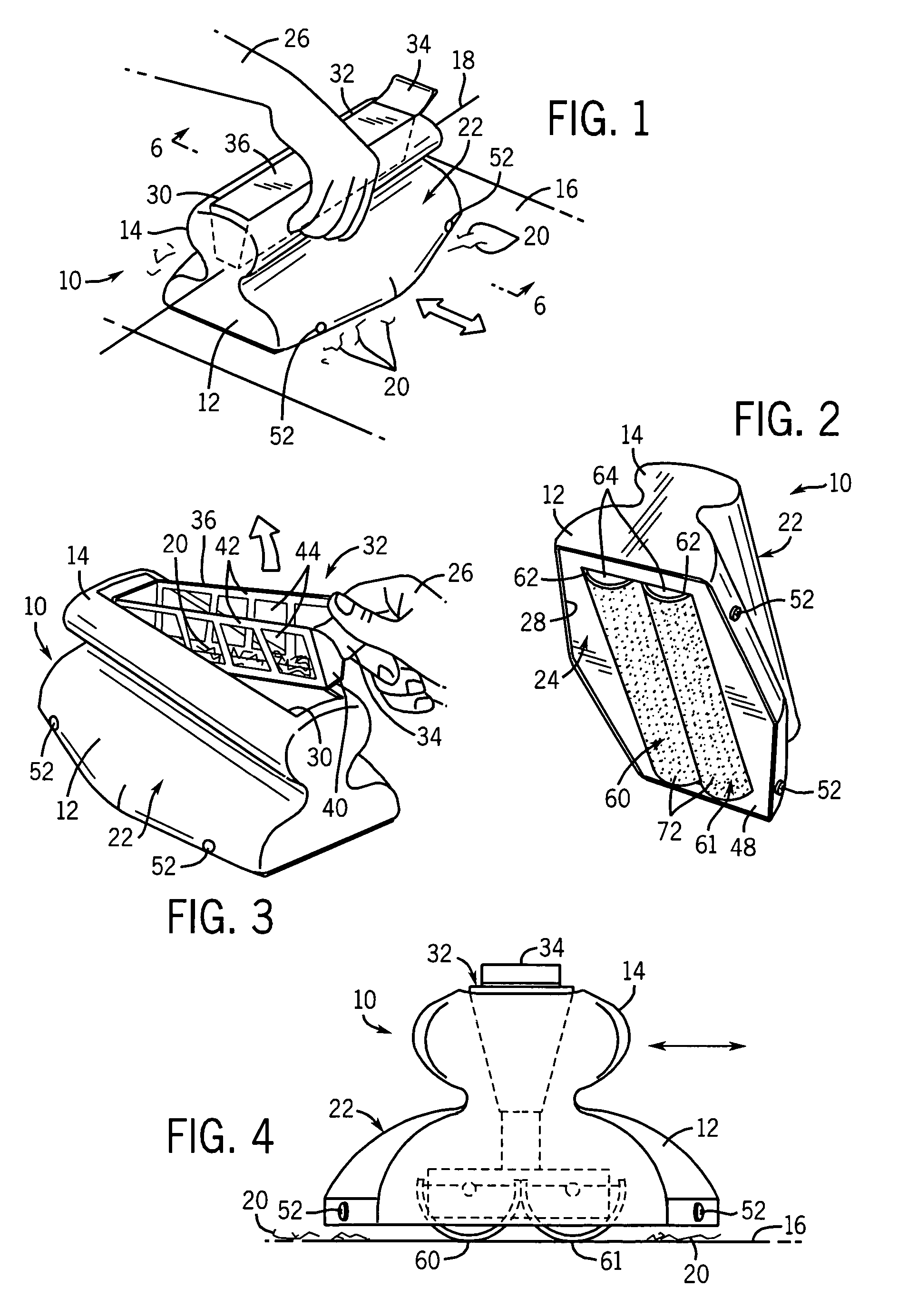
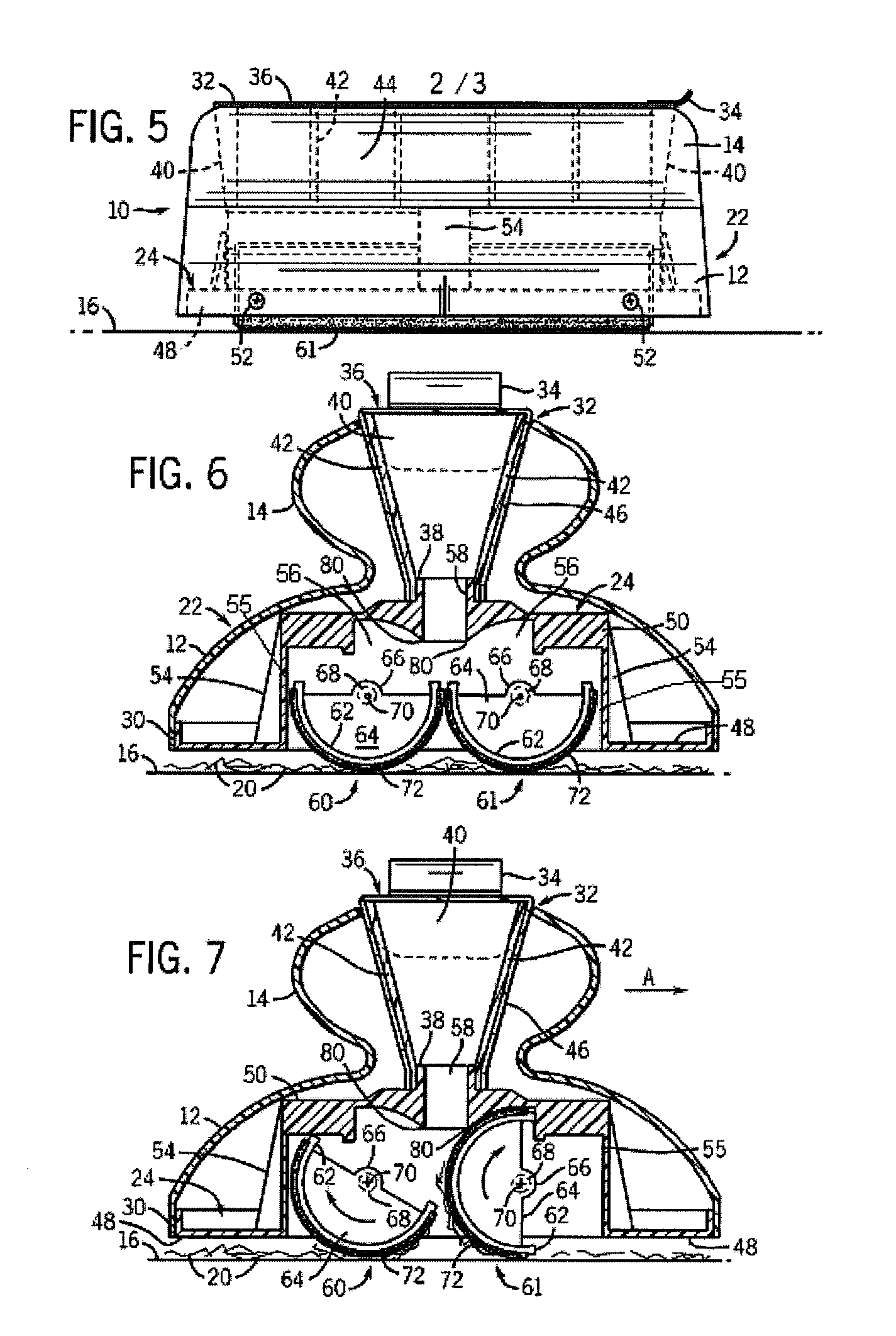
[0021]With reference now to the drawing figures in which like reference numerals designate like parts throughout the disclosure, a fabric cleaning device constructed according to the present invention is indicated generally at 10 in FIG. 1. The device 10 includes a base portion 12 and a handle portion 14 extending upwardly from the base portion 12. When in use, the base portion 12 of the device 10 is positioned on a fabric surface 16 and moved in a direction generally perpendicularly to the long axis 18 of the device 10 in order to pick up debris 20 disposed on the fabric surface 16.

[0022]Referring now to FIGS. 1-6, the device 10 is formed with an outer housing 22 and an inner housing 24. Both the outer housing 22 and inner housing 24 are formed of a generally rigid material, that is also preferably lightweight, in order to enable the device 10 to be easily manipulated by an individual's hand 26, as best shown in FIG. 1. Most preferably, each housing 22 and 24 is constructed of a pl...


PUM

PropertyMeasurementUnit
flexibleaaaaaaaaaa
transparentaaaaaaaaaa
semi-cylindrical shapeaaaaaaaaaa

Abstract

The present invention is a device for use in cleaning a fabric surface of dust, dirt, pet hair and other debris present on the surface. The device includes a pair of cleaning members or rollers disposed on an underside of the device which can roll with respect to the device and with respect to one another. The rollers are selectively contacted with one another such that each roller can assist in removing debris picked up by the opposite roller and dispensing the debris into a collection chamber releasably positioned within the housing. The removal of the debris from each roller is also facilitated by opposed edges of a central opening in the housing that contact the rollers and direct the debris into the debris collection chamber.

Description

FIELD OF THE INVENTION[0001]The present invention relates to cleaning devices, and more specifically to a cleaning device for fabrics that is capable of picking up and retaining for disposal various debris located on a fabric surface.BACKGROUND OF THE INVENTION[0002]When cleaning fabric surfaces, often times mechanical vacuum cleaning devices are utilized in order to effectively remove dirt, dust, and other debris from the fabric surface. However, due to the often large and cumbersome construction of these types of mechanical vacuum fabric cleaning devices, these devices are often not suitable for use in certain situations where the fabric surface to be cleaned is relatively small, or is positioned in a difficult to access location. In addition, for various instances of spot cleaning certain fabric surfaces, a large mechanical cleaning device is often impractical for the particular cleaning task.[0003]Therefore, in order to provide a lightweight cleaning device that can be utilized ...

Claims


Application Information

Patent Timeline
Patent Type & Authority Patents(United States)
IPC IPC(8): A47L25/00
CPCA47L11/33A47L11/4013A47L25/08A47L11/4041A47L11/4075A47L11/4025
Inventor KNOPOW, JEREMY F.SMITS, CHRISSIE M.
Owner SC JOHNSON & SON INC
Why Eureka
Try Eureka