Vehicle suspension system with roll stiffness distribution control

a technology of suspension system and roll stiffness, which is applied in the direction of cycle equipment, instruments, transportation and packaging, etc., can solve the problems of insufficient driving performance of the actuator on the front-wheel side and insufficient driving performance of the actuator on the rear-wheel side, so as to prevent or suppress an undesirable

Active Publication Date: 2010-05-25
TOYOTA JIDOSHA KK
View PDF35 Cites 11 Cited by
  • Summary
  • Abstract
  • Description
  • Claims
  • Application Information

AI Technical Summary

Benefits of technology

[0010]It is an object of the invention to provide a suspension system which can prevent or suppress an undesirable change in a steer characteristic due to insufficient driving performance of an actuator.
[0014]In the suspension system according to the first aspect of the invention, for example, when the driving performance of the actuator of the front roll stiffness changing device is insufficient, and therefore the roll stiffness on the front-wheel side is insufficient, the target roll stiffness correspondence amount on the rear-wheel side is determined according to the actual roll stiffness correspondence amount on the front-wheel side. Alternatively, when the driving performance of the actuator of the rear roll stiffness changing device is insufficient, and therefore, the roll stiffness on the rear-wheel side is insufficient, the target roll stiffness correspondence amount on the front-wheel side is determined according to the actual roll stiffness correspondence amount on the rear-wheel side. That is, the target roll stiffness correspondence amount on the front-wheel side or the rear-wheel side where the driving performance of the actuator is sufficient is reduced. As a result, the roll stiffness distribution ratio between the front-wheel side and the rear-wheel side becomes an appropriate value, or comes close to an appropriate value. This prevents or suppresses an undesirable change in the steer characteristic.
[0028]The operation amount of the actuator corresponds one-to-one with the actual roll stiffness (for example, the operation amount of the actuator is proportional to the actual roll stiffness). Therefore, it is appropriate to use the operation amount of the actuator as the actual roll stiffness correspondence amount. Further, an actuator operation amount obtaining portion is usually provided for controlling the actuator. By providing the actuator operation amount obtaining portion, the need for providing a dedicated device for obtaining the actual roll stiffness correspondence amount is eliminated, which makes it possible to achieve the object at low cost.

Problems solved by technology

In another aspect, only the driving performance of the actuator on the front-wheel side may become insufficient and the driving performance of the actuator on the rear-wheel side is always sufficient.
In yet another aspect, only the driving performance of the actuator on the rear-wheel side may become insufficient and the driving performance of the actuator on the front-wheel side is always sufficient.

Method used


Image

  • Vehicle suspension system with roll stiffness distribution control
  • Vehicle suspension system with roll stiffness distribution control
  • Vehicle suspension system with roll stiffness distribution control

Examples


Embodiment Construction

[0047]Hereinafter, embodiments of the invention will be described in detail with reference to the drawings. The invention can be realized also in other embodiments where various modifications are made based on the knowledge of persons skilled in the art.

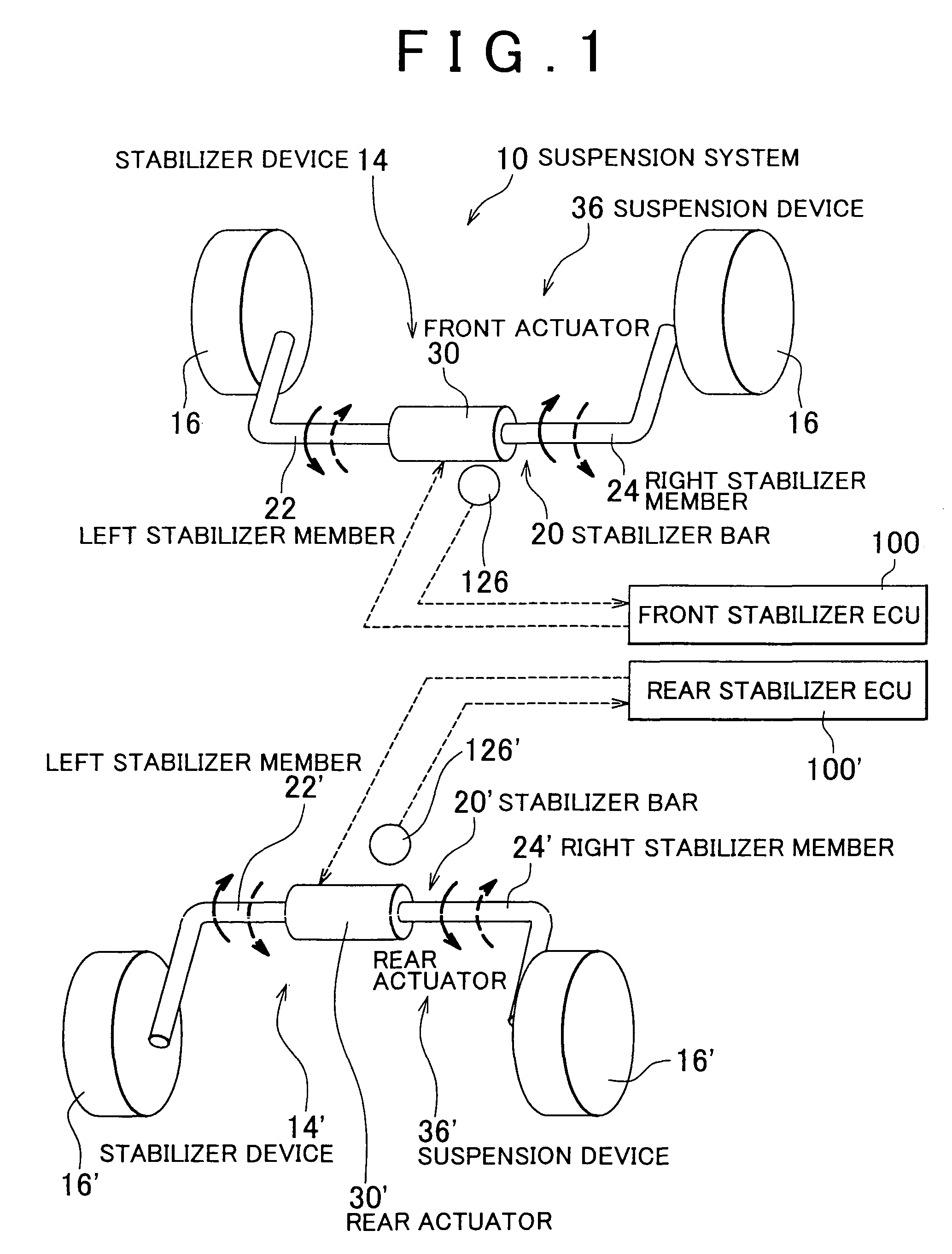
[0048]FIG. 1 illustrates a diagram that conceptually shows a portion of a suspension system according to an embodiment of the invention. A suspension system 10 includes two stabilizer devices 14, 14′ that suppress rolling of a vehicle (hereinafter, reference numerals indicating components on the rear-wheel side are apostrophized). The stabilizer devices 14, 14′ are provided on the front-wheel side and on the rear-wheel side, respectively. The stabilizer devices 14, 14′ include stabilizer bar 20, 20′ respectively. The stabilizer bar 20 is connected, at both ends thereof, to wheel-holding members that hold front-left and front-right wheels 16; and the stabilizer bar 20′ is connected, at both ends thereof, to wheel-holding members that ...


PUM


Abstract

In a target rotational angle determining routine, based on a roll moment and longitudinal acceleration that are calculated, target rotational angles of actuators on a subject side (one of front-wheel and rear-wheel sides) and a counterpart side are obtained using a common map. An actual rotational angle on the counterpart side is read. It is determined whether the absolute value of a difference obtained by subtracting the actual rotational angle supplied from the counterpart side from the target rotational angle on the counterpart side that is obtained by the subject side is equal to or greater than a set angle difference Δθ0. If YES, it is determined that roll stiffness on the counterpart side is insufficient, and the target rotational angle on the subject side is changed so that a roll stiffness distribution ratio between the front-wheel side and the rear-wheel side comes close to a set distribution ratio.

Description

INCORPORATION BY REFERENCE[0001]The disclosure of Japanese Patent Application No. 2005-75701 filed on Mar. 16, 2005, including the specification, drawings and abstract, is incorporated herein by reference in its entirety.BACKGROUND OF THE INVENTION[0002]1. Field of the Invention[0003]The invention relates to a suspension system of a vehicle, and more particularly to a suspension system which can control roll stiffness distribution between a front-wheel side and a rear-wheel side.[0004]2. Description of Related Art[0005]Each of Japanese Patent Application Publications No. JP-A-7-186674, No. JP-A-7-32845, and No. JP-A-5-319055 describes a suspension system which can control roll stiffness distribution. For example, the suspension system described in Japanese Patent Application Publication No. JP-A-7-186674 includes a front roll stiffness changing device; a rear roll stiffness changing device; a roll moment distribution estimating device; and a roll stiffness distribution control devic...

Claims


Application Information

Patent Timeline
Patent Type & Authority Patents(United States)
IPC IPC(8): B60G17/016
CPCB60G17/0162B60G21/0555B60G21/0558B60G2202/135B60G2202/42B60G2204/62B60G2204/419B60G2400/98B60G2600/08B60G2800/0122B60G2800/24B60G2800/9122B60G2204/8302B60G17/015B60G17/016
Inventor URABABA, SHINGOIIDA, TOMOYUKI
Owner TOYOTA JIDOSHA KK
Why Eureka
Try Eureka