
Training bat with visual feedback of proper swing

a training bat and proper swing technology, applied in the field of baseball bats, can solve the problems of difficult to learn the proper swing skill, the muscle coordination necessary to execute a superior swing is dauntingly complex, and the muscle coordination is further complicated

Inactive Publication Date: 2010-06-01
GANT RICHARD ALVA
View PDF25 Cites 65 Cited by
  • Summary
  • Abstract
  • Description
  • Claims
  • Application Information

AI Technical Summary

Benefits of technology

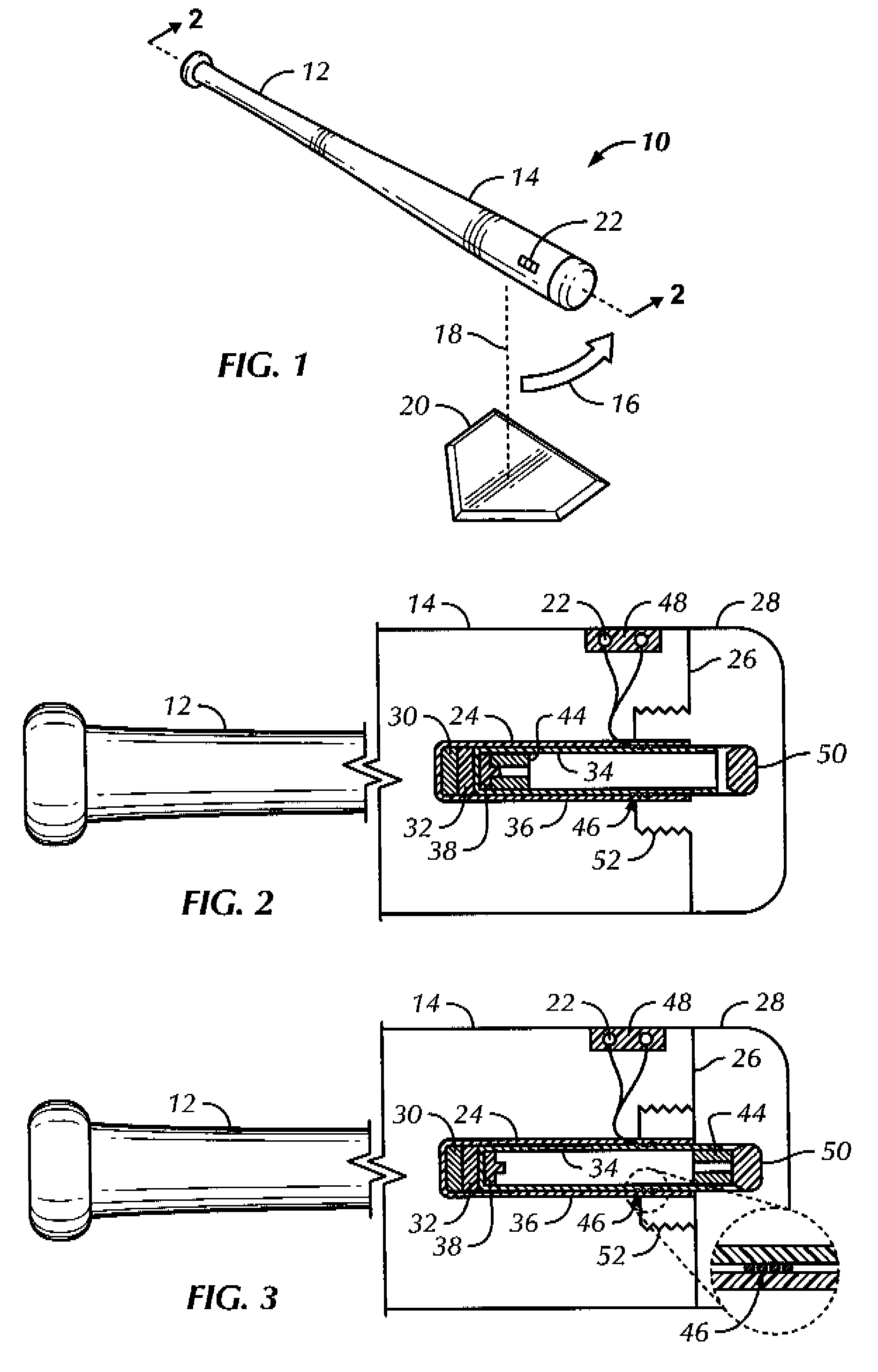
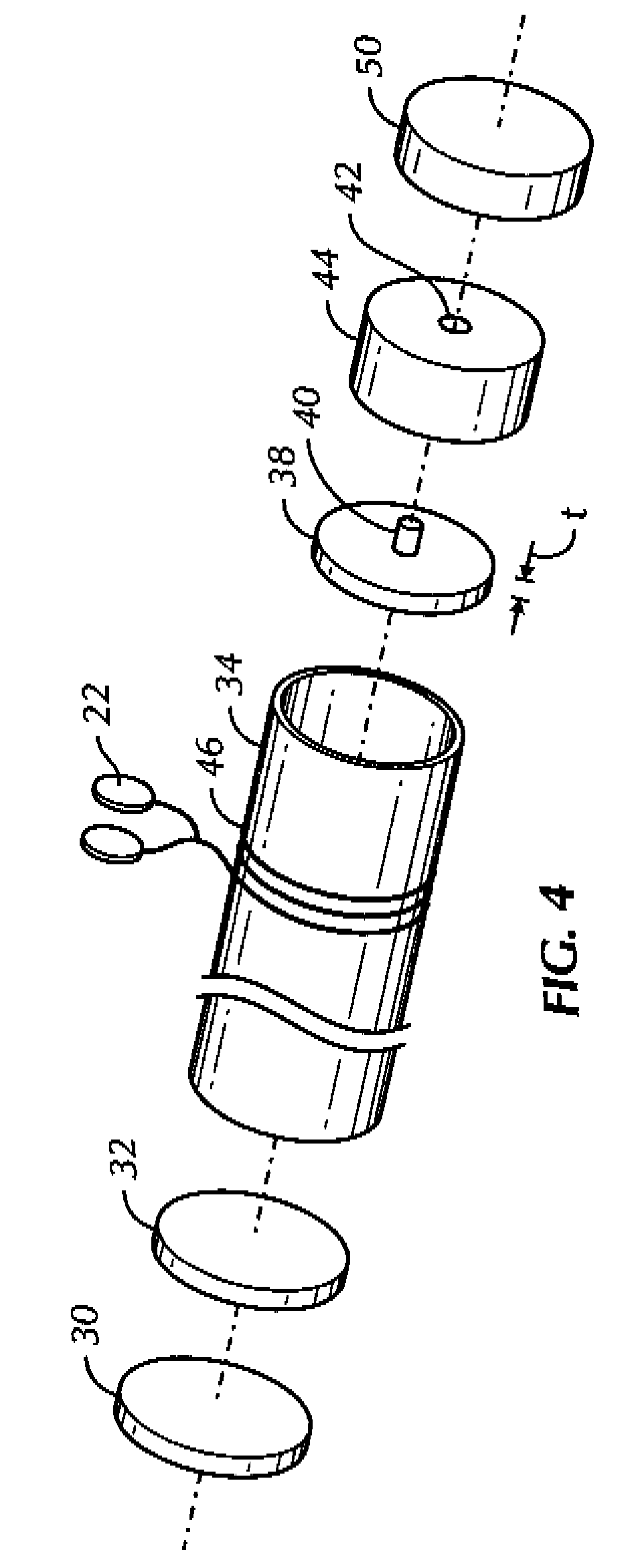
"The patent describes a baseball training device that includes a barrel with a channel and a movable magnet. The magnet can move between a housed position and a swung position. When the magnet moves, a temporary electrical signal is induced in a wire coil surrounding the channel. The device also includes light emitting diodes (LEDs) mounted on the barrel that emit a flash of light when the magnet moves through the coil. The device can help train a person to swing the bat at a preferred speed. Additionally, the patent describes a non-limiting implementation where the stationary magnet is held in the channel by epoxy, and a tube and cap can be used to hold the movable magnet. The patent also describes a kit that includes a handle, barrel, and a movable magnet. The movable magnet can move between the housed position and the swung position when sufficient centrifugal force is applied. The device can help improve the swing speed and accuracy of the batter."

Problems solved by technology

A properly executed baseball swing is a difficult skill to learn, because while swing mechanics can be told to a batter, the muscle coordination necessary to execute a superior swing is dauntingly complex.
The muscular coordination is further complicated by the fact that the head and shoulders must cooperate with the torso and hips to accelerate the bat through the contact point while maintaining the focus of the eyes on the ball at the point of contact.

Method used


Image

  • Training bat with visual feedback of proper swing
  • Training bat with visual feedback of proper swing
  • Training bat with visual feedback of proper swing

Examples


Embodiment Construction

[0016]Referring initially to FIG. 1, a training bat is shown, generally designated 10, which includes a handle 12 connected to a barrel 14. The bat 10 may be made of wood or metal or composite materials and may be a conventional bat altered in accordance with present principles.

[0017]As shown in FIG. 1, visible indication can be provided on the barrel 14 of the barrel 14 being swung in a preferred swing plane described by the arc 16 at or greater than an acceptable speed as it passes through an imaginary vertical line 18 intersecting a preferred location in the arc, typically just in front of a home plate 20 next to which a batter in training typically would stand (FIG. 1 assumes a right-handed swing). The visible indication, however is not provided if the barrel 14 passes through the imaginary vertical line 18 at less than the acceptable speed.

[0018]In the embodiment shown in FIG. 1, the visible indication is a flash of light generated by a source of light such as one or more lamps...


PUM


Abstract

A training baseball bat has an internal movable magnet that accelerates to the end of the bat when swung at a fast enough speed. As the magnet moves it passes through a coil that is connected to one or more LEDs so that the LEDs momentarily flash as the magnet moves through the coil. A stationary magnet can be used to hold the movable magnet until sufficient centrifugal force is imparted by the swing to overcome the magnetic holding force. Spacers can be provided to establish a distance between the magnets as needed to establish a desired swing speed at which centrifugal force overcomes the magnetic attraction.

Description

[0001]This application claims priority to U.S. provisional patent application 60 / 942,055, filed Jun. 5, 2007, incorporated herein by reference.I. FIELD OF THE INVENTION[0002]The present invention relates generally to baseball bats used for training purposes.II. BACKGROUND OF THE INVENTION[0003]A properly executed baseball swing is a difficult skill to learn, because while swing mechanics can be told to a batter, the muscle coordination necessary to execute a superior swing is dauntingly complex. First, to impart optimum power the bat should be swung in an optimum swing plane that is substantially horizontal, i.e., it ideally exhibits a slight uppercut a few degrees from horizontal, although depending on ball location, other swing planes may be used.[0004]But not only must the bat swing follow a preferred swing plane, the speed of the bat head should be at an acceptably high magnitude at a particular point in the plane, namely, the point at which contact with the ball is made. While ...

Claims


Application Information

Patent Timeline
Patent Type & Authority Patents(United States)
IPC IPC(8): A63B69/00
CPCA63B59/06A63B69/0002A63B59/0092A63B2209/08A63B2071/0625A63B2207/02A63B2209/02A63B2069/0008A63B59/50A63B59/59A63B60/54A63B2102/18A63B2225/74
Inventor GANT, RICHARD ALVA
Owner GANT RICHARD ALVA
Learn More