Back brace having pull cord for size adjustment

a pull cord and size adjustment technology, applied in the field of back braces, can solve the problems of high effort required to direct pull the soft elastic belt to the desired tightness, difficult adjustment operation for elderly people, women or patients who do not have great strength, and use of expensive electronic components by electromechanical means. , to achieve the effect of less effor

Inactive Publication Date: 2010-06-01
KAO CHEN ENTERPRISE
View PDF5 Cites 52 Cited by
  • Summary
  • Abstract
  • Description
  • Claims
  • Application Information

AI Technical Summary

Benefits of technology

[0006]The present invention has been accomplished under the circumstances in view. It is the primary objective of the present invention to provide a back brace, which allows adjustment of the tightness subject to the desired tension conveniently with less effort.
[0007]It is another objective of the present invention to provide a back brace, which has a simple structure and is inexpensive to manufacture.

Problems solved by technology

Directly pulling the soft elastic belt to the desired tightness requires much effort.
This adjustment operation is somewhat difficult to an old person, woman or patient who does not have great strength.
However, the electromechanical means uses expensive electronic component parts, and has a complicated structure.
Because of high sale price, this design of back brace apparatus cannot be popularly accepted.

Method used


Image

  • Back brace having pull cord for size adjustment
  • Back brace having pull cord for size adjustment
  • Back brace having pull cord for size adjustment

Examples


Embodiment Construction

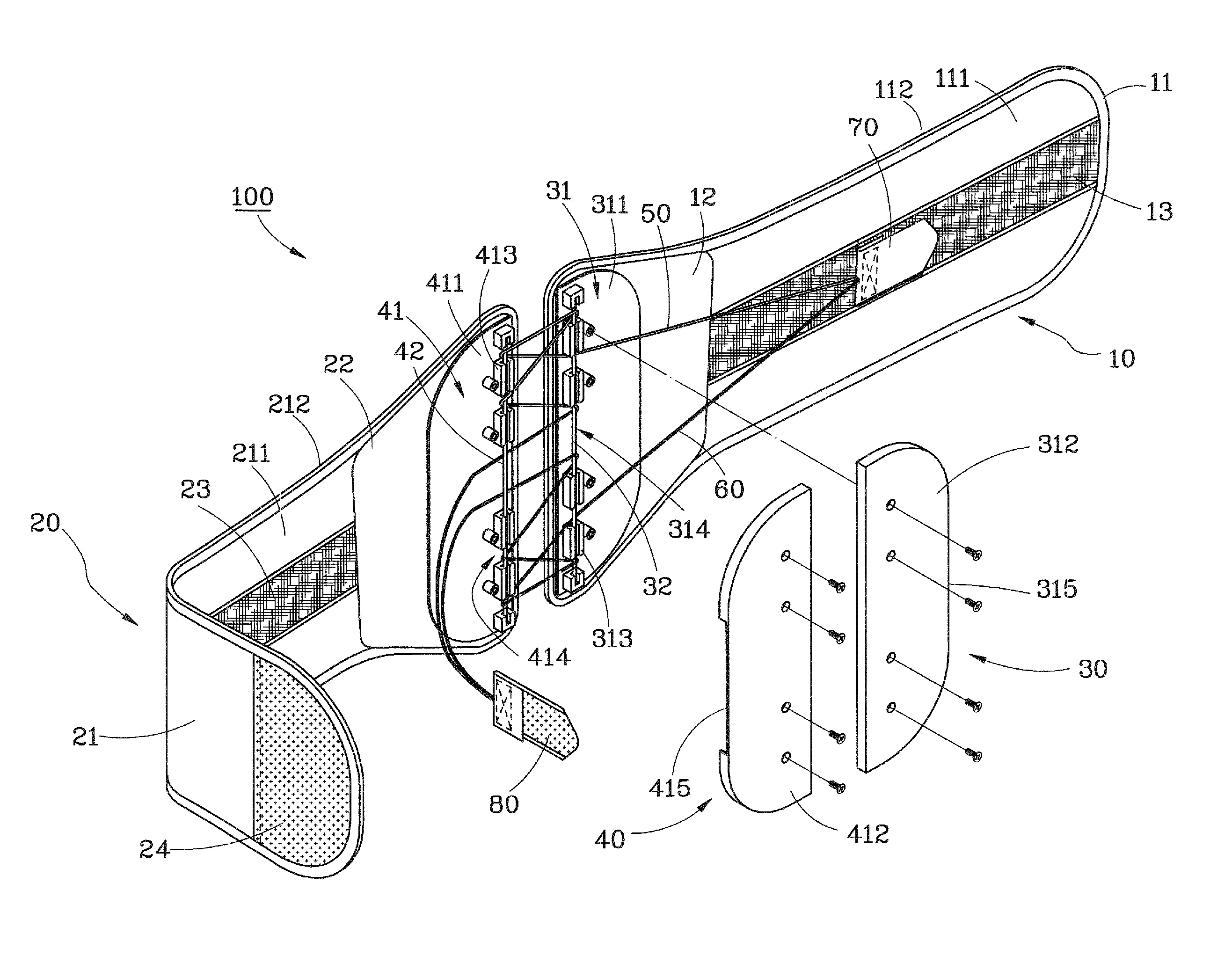
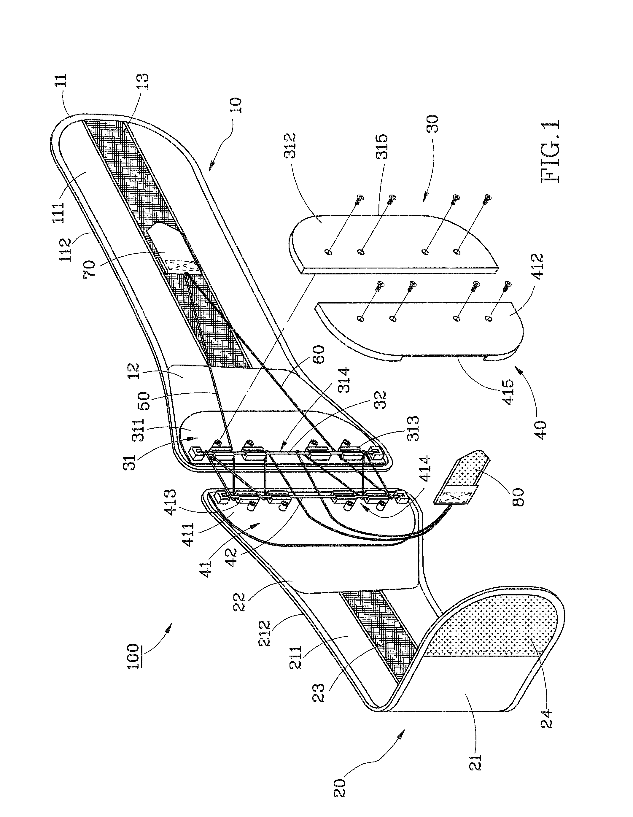
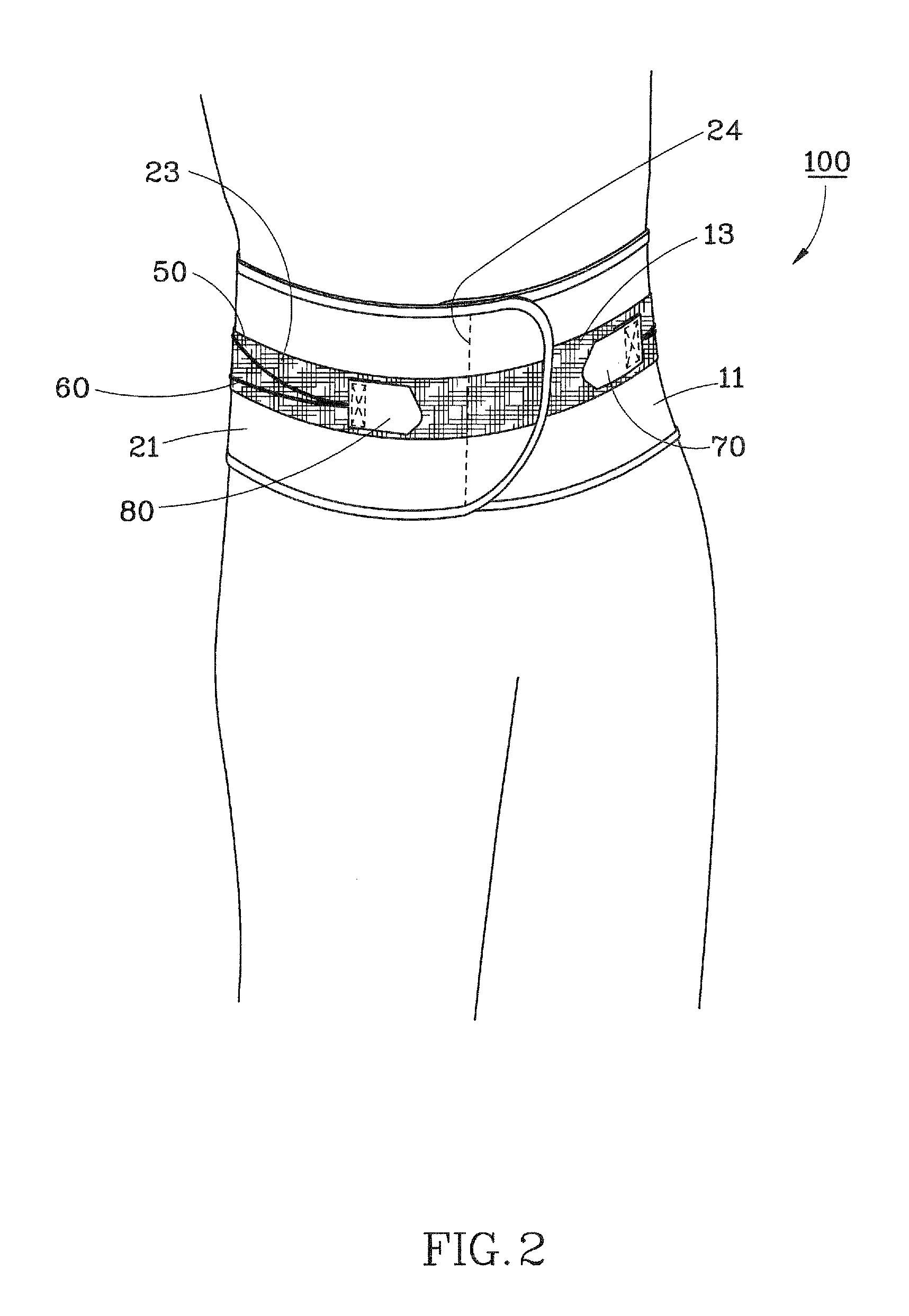
[0015]Referring to FIGS. 1-4, a back brace 100 in accordance with a preferred embodiment of the present invention comprises a first brace member 10, a second brace member 20 a first adjustment holder 30, a second adjustment holder 40 two pull cords 50 and 60 and two fastening members 70 and 80.

[0016]The first brace member 10 comprises a first belt body 11, a first support plate 12, and a first connector 13. The first belt body 11 is made out of a soft, slightly elastic, flexible material, defining a first outer surface 111 and a first inner surface 112 opposite to the first outer surface 111. The first support plate 12 is a hard member fixedly fastened to the first outer surface 111 adjacent to one end of the first belt body 11. The first connector 13 is a tape of loop member of a hook and loop fastener fixedly mounted on and extending along the major axis of the first belt body 11.

[0017]The second brace member 20 comprises a second belt body 21, a second support plate 22, a second ...


PUM


Abstract

A back brace includes a first brace member having a first connector, and a second brace member having a second connector and a coupler at two opposite sides thereof. The coupler is detachably connectable to the first connector. A first adjustment holder is affixed to one end of the first brace member and holds therein a first rod member. A second adjustment holder is affixed to one end of the second brace member and holds therein a second rod member. Two pull cords are inserted through the first adjustment holder and the second adjustment holder and run alternately back and forth over the first rod member and the second rod member to adjustably and abuttably hold the first and second brace members side by side. Two fastening members are fastened to distal ends of the pull cords and detachably connectable to the first and second connectors.

Description

BACKGROUND OF THE INVENTION[0001]1. Field of the Invention[0002]The present invention relates to a back brace for supporting the back of a person and more particularly to a back brace having pull cords for size adjustment.[0003]2. Description of the Related Art[0004]A regular back brace is generally formed of a soft elastic belt for wearing around the waist or abdomen of a person and a tape of hook member and a tape of loop member of a hook and loop fastener respectively provided at two opposite sides of the soft elastic belt for securing the soft elastic belt to the body of a person. When the user wants to adjust the tightness of the soft elastic belt subject to the desired tension, the user must separate the tape of hook member and the tape of loop member, and then pull the soft elastic belt to the desired tightness, and then fasten the tape of hook member and the tape of loop member together. Directly pulling the soft elastic belt to the desired tightness requires much effort. Th...

Claims


Application Information

Patent Timeline
Patent Type & Authority Patents(United States)
IPC IPC(8): A61F5/00
CPCA61F5/028
Inventor WANG, CHIH-CHUAN
Owner KAO CHEN ENTERPRISE
Why Eureka
Try Eureka