Strain-responsive visual indicator

a visual indicator and responsive technology, applied in the field of sensing and sensing, can solve the problems of affecting the quality and affecting the condition of teeth and gums. , the surface of teeth can also become damaged irreparably, and the brushing of teeth too hard can be detrimental to the condition of teeth and gums

Inactive Publication Date: 2010-06-08
QINETIQ LTD
View PDF26 Cites 20 Cited by
  • Summary
  • Abstract
  • Description
  • Claims
  • Application Information

AI Technical Summary

Problems solved by technology

In this respect it is well documented that brushing the teeth too hard can be detrimental to the condition of the teeth and gums.
If teeth are brushed too hard the gums can start to recede causing bleeding of the gums and sensitive teeth.
The surface of the teeth can also become damaged irreparably.

Method used


Image

  • Strain-responsive visual indicator
  • Strain-responsive visual indicator
  • Strain-responsive visual indicator

Examples


Embodiment Construction

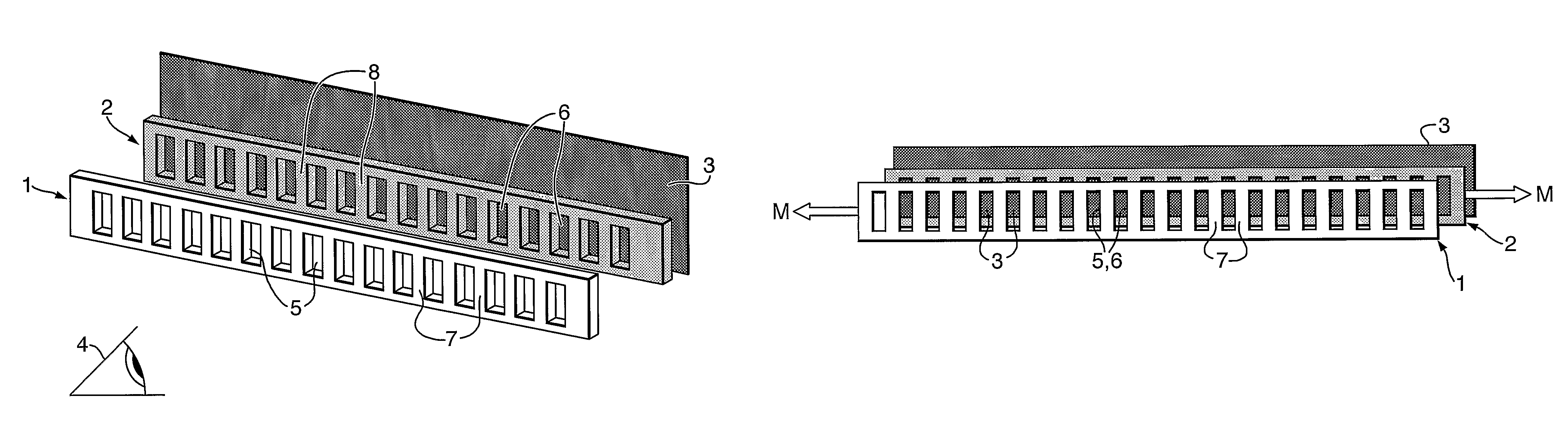
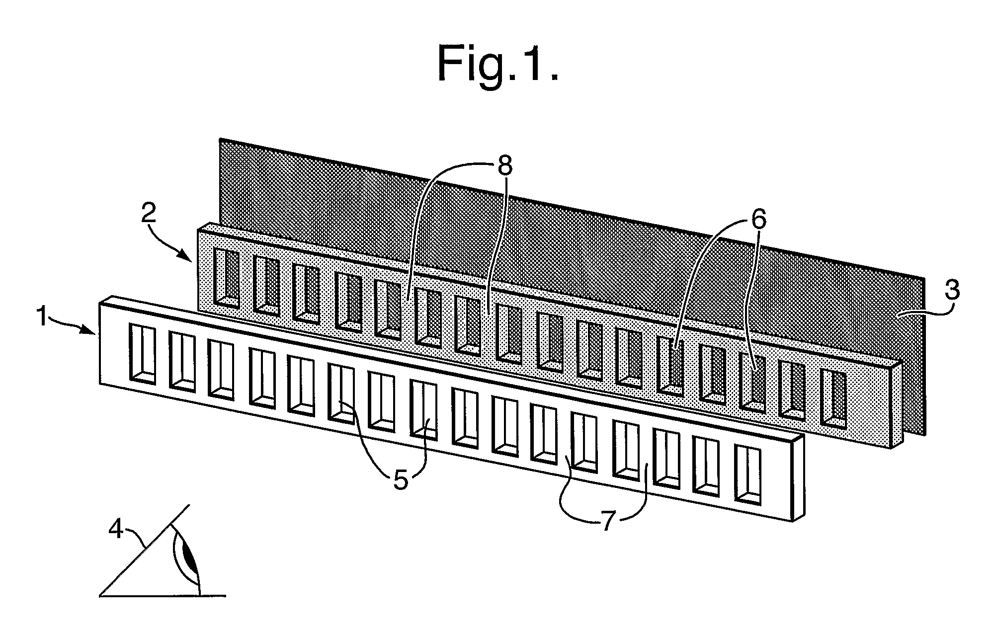
[0031]Referring to FIG. 1, the basic components of the illustrated indicator comprise a pair of shutter strips 1 and 2 and a backing strip 3. The strips 1 and 2 are shown separated from each other for ease of illustration in this Figure but in the assembled indicator will lie closely one behind the other as viewed from the direction of the eye symbol 4. Each shutter strip 1 and 2 comprises a similar longitudinal series of equi-spaced windows 5, 6, in this embodiment shown as perforations through the thickness of the material of the strips, separated by bars of the respective strip material 7,8. The windows 5,6 and bars 7,8 in both strips 1 and 2 are all of substantially the same width (dimension in the longitudinal direction of the respective strip).

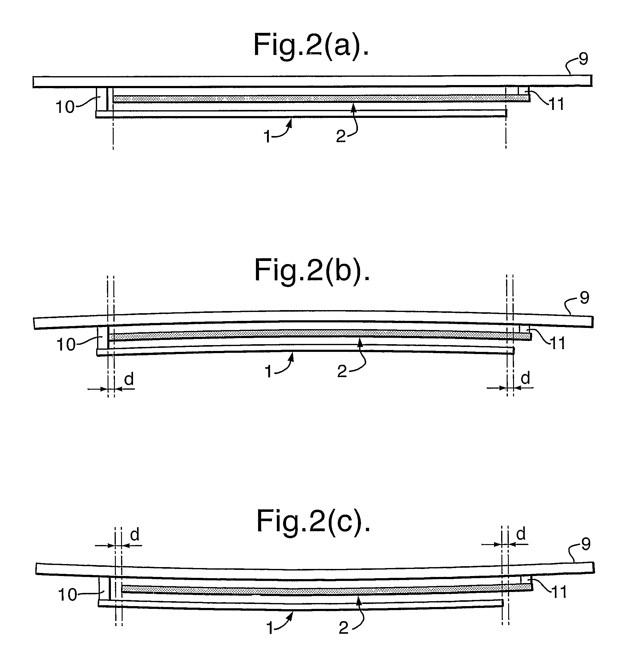
[0032]FIG. 2 illustrates the mounting of these strips to indicate strain in a substrate 9. Strips 1 and 2 are anchored to the substrate by respective fixtures 10 and 11 at opposite respective ends so that expected strain in the substrate...


PUM


Abstract

A strain-responsive visual indicator comprises a pair of overlapping shutter strips (1, 2) adapted to be mounted to a substrate such that strain in the substrate causes relative movement M between them. Each shutter strip comprises an alternating set of windows (5) or (6) and bars (7) or (8) and the distal strip (2) is backed by a strip (3) of a different color exposed through its windows (6), or the distal strip can instead be printed with a set of alternating colors in place of its windows and bars. The effect is that under different strain conditions different color indications from the distal strip (2) will be visible through the windows (5) of the proximal strip (1), in accordance with the relative positions of the two strips. The indicator can be incorporated e.g. in the shaft of a toothbrush to give a visual warning in response to flexure of the shaft if excessive brushing pressure is applied. Numerous other applications and the use of different types of indicia are indicated in the specification.

Description

BACKGROUND OF THE INVENTION[0001](1) Field of the Invention[0002]The present invention relates to the general field of strain measurement or sensing.[0003](2) Description of the Art[0004]Conventional strain gauges take a variety of forms and among the most common are resistance strain gauges which exploit the change in resistance of an electrically conductive material when the conductor is stretched or otherwise elastically deformed, and semiconductor strain gauges which exploit the change in the electronic charge across a piezoelectric crystal when the material is mechanically stressed. Such types obviously require the use of associated electronic monitoring equipment in order to give an indication of the measured strain. Purely mechanical strain gauges are also known but generally require precision mechanisms to amplify the small movements sensed and to convert them into an indication of strain. The present invention, on the other hand, seeks to provide a simple and inexpensive fo...

Claims


Application Information

Patent Timeline
Patent Type & Authority Patents(United States)
IPC IPC(8): G01B11/16A46B15/00B26B21/40G01B5/30
CPCA46B15/0002A46B15/0006A46B15/0012G01L5/0028B26B19/388B60C23/06G01D7/005B26B19/38Y10S116/34
Inventor PETT, MARTIN ANDREWJAMIESON, IAN ANDREW
Owner QINETIQ LTD
Why Eureka
Try Eureka