Method and apparatus for pseudo-projection formation for optical tomography

a technology of optical tomography and pseudo-projection, applied in the field of optical systems, can solve the problems of large amount of computer memory, limited spatial resolution that can be achieved, and scattering can become a significant problem, and achieve the effect of reducing scattered ligh

Active Publication Date: 2010-06-15
UNIV OF WASHINGTON +1
View PDF89 Cites 120 Cited by
  • Summary
  • Abstract
  • Description
  • Claims
  • Application Information

AI Technical Summary

Problems solved by technology

Such scattering can become a significant problem when the scattered photon intensity in any given detector element exceeds that of the signal-to-noise limit in the reconstruction process.
Furthermore, the spacing between each focal plane places a limit on the spatial resolution that can be achieved, and storage of the separate images requires large amounts of computer memory.
In addition, out-of-focus light from the other focal planes contributes to undesirable spurious signals (blurring) in the assembled image.
Sample preparation has also been problematic for prior methods.
For example, others have had problems with simple vacuum-based insertion of cells or relying on capillary action to wick-up the cell suspension.

Method used


Image

  • Method and apparatus for pseudo-projection formation for optical tomography
  • Method and apparatus for pseudo-projection formation for optical tomography
  • Method and apparatus for pseudo-projection formation for optical tomography

Examples


Embodiment Construction

General Embodiments

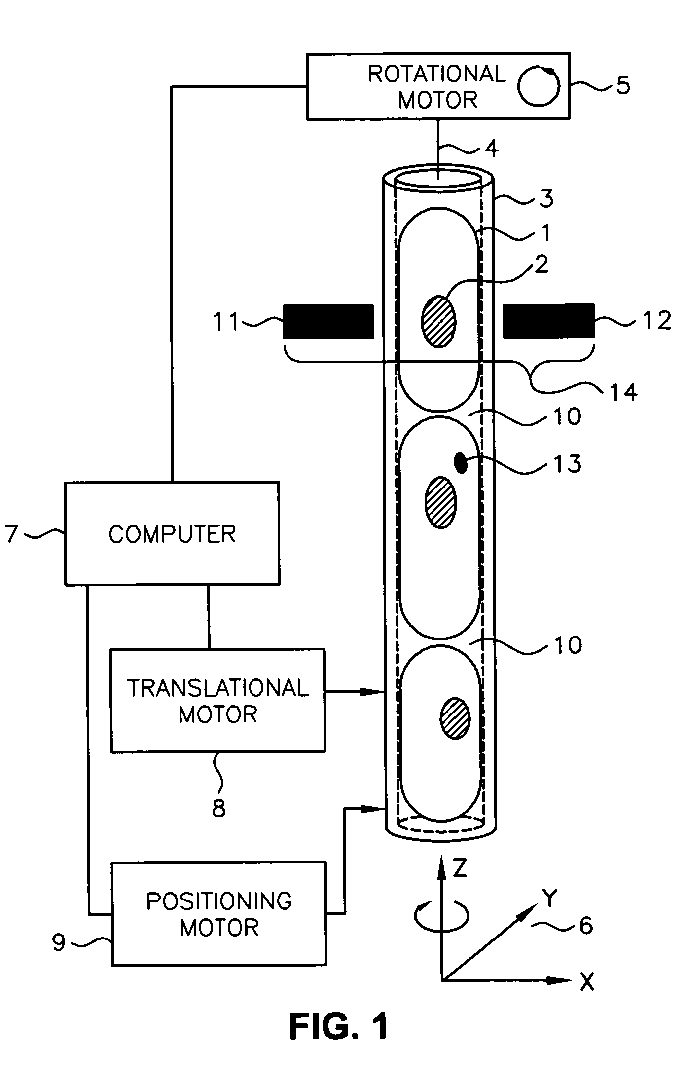
[0036]Referring now to FIG. 1, there shown schematically is an example illustration of cells packed into a capillary tube as contemplated by an embodiment of the present invention. In this example embodiment, a section of the capillary tube 3 is filled with cells 1 that are packed rigidly into the tube. Each of the cells may include a nucleus 2. The capillary tube 3 has a central axis 4 oriented with reference to a coordinate system 6 having coordinates in the x, y and z-directions. In some instances, at least one molecular probe 13 may be bound within the cell. A computer 7 is coupled to provide control signals to a rotational motor 5 and a translational motor 8. It will be recognized that equivalent arrangements of one or more motors, gears or fluidics or other means of generating motion may also be employed to achieve the necessary translational and rotational motion of the capillary tube or other substrate. In some cases, one or more of the motors may be repla...


PUM

PropertyMeasurementUnit
diameteraaaaaaaaaa
diameteraaaaaaaaaa
lengthaaaaaaaaaa

Abstract

A system for optical imaging of a thick specimen that permits rapid acquisition of data necessary for tomographic reconstruction of the three-dimensional (3D) image. One method involves the scanning of the focal plane of an imaging system and integrating the range of focal planes onto a detector. The focal plane of an optical imaging system is scanned along the axis perpendicular to said plane through the thickness of a specimen during a single detector exposure. Secondly, methods for reducing light scatter when using illumination point sources are presented. Both approaches yield shadowgrams. This process is repeated from multiple perspectives, either in series using a single illumination / detection subsystem, or in parallel using several illumination / detection subsystems. A set of pseudo-projections is generated, which are input to a three dimensional tomographic image reconstruction algorithm.

Description

RELATED APPLICATIONS[0001]This application is a continuation-in-part (CIP) of co-pending U.S. patent application Ser. No. 10 / 126,026, filed Apr. 19, 2002, of Nelson entitled “Variable Motion Optical Tomography of Small Objects,” which is incorporated herein by this reference.FIELD OF THE INVENTION[0002]The present invention is related to optical systems and, more particularly, to optical systems for extended depth-of-field imaging through a thick specimen (i.e. non-planar) to generate shadowgrams, wherein the apparatus permits the rapid acquisition of data necessary for tomographically reconstructing the three dimensional (3D) image of a specimen useful in applications such as high-resolution optical tomography of micron-scale objects.BACKGROUND OF THE INVENTIONOverview[0003]For some imaging applications, it is desirable to generate information in three dimensions within a thick specimen. An optical tomographic device is intended to produce three-dimensional reconstructions of speci...

Claims


Application Information

Patent Timeline
Patent Type & Authority Patents(United States)
IPC IPC(8): A61B5/05G01N21/17A61B10/00G01N15/14G01N21/03G01N21/05G01N21/21G01N21/47G06T
CPCG01N15/1468G01N15/1475G01N21/05G01N21/4795G06T11/006G01N15/147G01N2015/1006G06T2211/421G01N2015/1447G01N2021/0346G01N2021/1787G01N2201/0813G01N2223/612G01N2015/1075
Inventor FAUVER, MARK E.RAHN, J. RICHARDSEIBEL, ERIC J.NELSON, ALAN C.
Owner UNIV OF WASHINGTON
Why Eureka
Try Eureka