
Spatio-temporal light field cameras

a spatial-temporal light field and camera technology, applied in the field of light field cameras and radiance cameras, can solve the problems of inability to integrate advanced auto focusing capabilities poor performance and excessive added cost of incorporating advanced auto focusing features into cameras targeting mobile devices, and current state-of-the-art light field cameras are inherently bulky in themselves and not at all suited for being embedded in mobile devices

Inactive Publication Date: 2015-11-03
OSTENDO TECH INC
View PDF103 Cites 34 Cited by
  • Summary
  • Abstract
  • Description
  • Claims
  • Application Information

AI Technical Summary

Benefits of technology

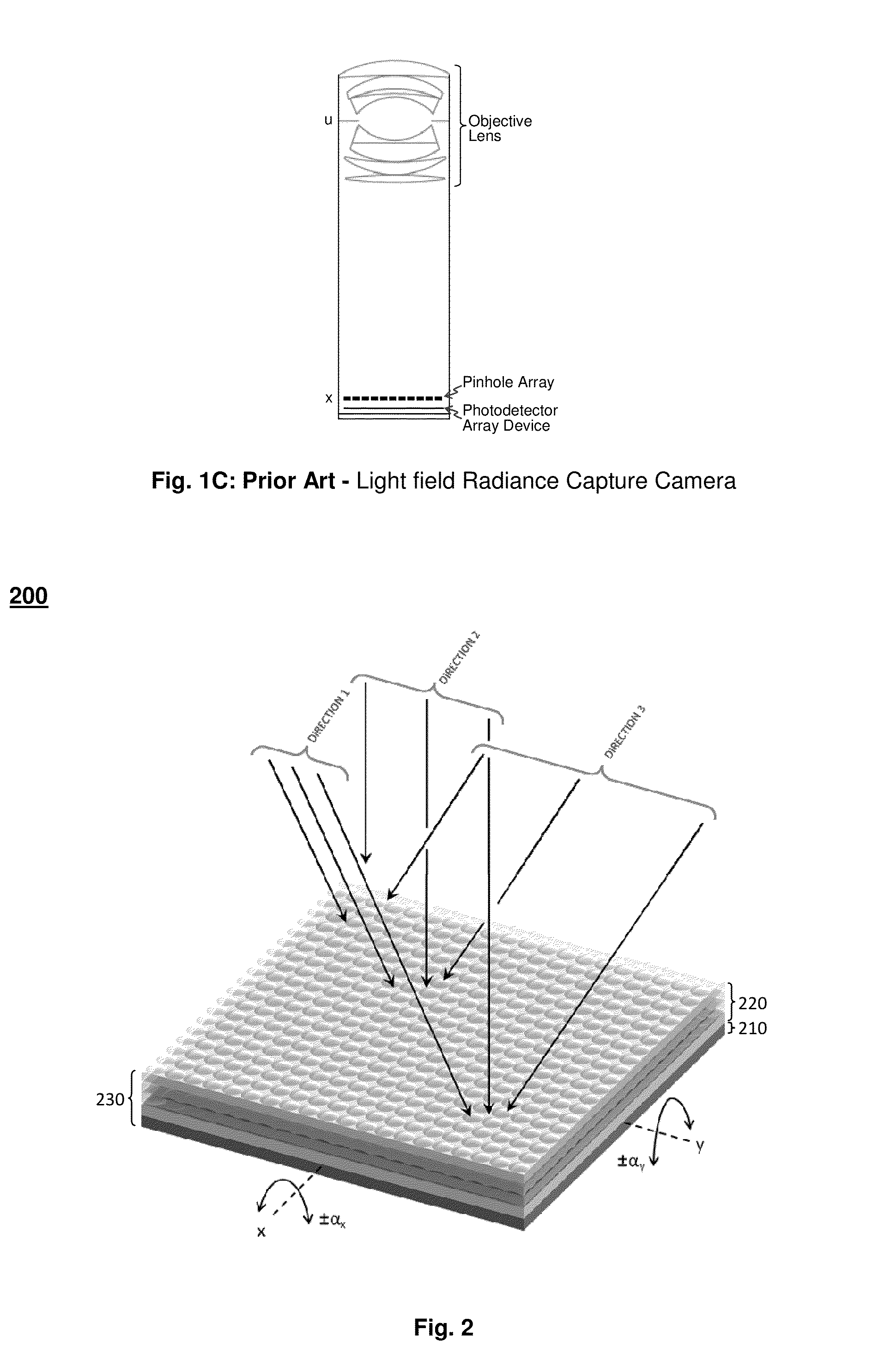
[0089]As stated earlier, the volumetric advantages of the spatio-temporal light field cameras of this invention make it possible to embed such a camera in mobile devices such cell phones and tablet PC. Since most all of such host mobile devices are typically interconnected either through wireless or wireline networks or through bulk data transfer using flash memory modules, it is possible to leverage such connectivity to further extend the light field captured by the light field cameras of this invention. In this embodiment, the output of a multiplicity of embedded spatio-temporal light field cameras of this invention located in the surroundings of a viewing scene that captured light field images of the viewing scene, as illustrated in FIG. 13, will have the data representing the light field it captured (described in FIG. 11). That data can be augmented with three additional data fields by application software incorporated into the operating system of the host mobile device. The first data field would specify the camera location, which would typically be the output of the location sensing device also embedded in the host mobile device, such as a global positioning system (GPS) receiver or triangulated wireless link; the second data field would specify the orientation of the mobile device, and thus the orientation of its embedded camera, which would typically be the output of an orientation sensing device also embedded in the mobile device, such as the micro gyros typically embedded in mobile devices for adapting the display screen orientation and for gaming; and the third data field would specify the time the light field of the viewing scene is captured by the camera, which would typically be the output of the internal mobile device clock which is typically kept synchronized with a network time. When this augmented light field data is exchanged with other mobile devices also having an embedded spatio-temporal light field camera of this invention that has captured the light field of the scene viewed from a different perspective, it would be possible to integrate the exchanged light field data captured by the multiplicity of such cameras and computationally fuse it together into a single super light field data set that represent the collective light field captured by all the embedded cameras that captured a partial perspective of the viewing scene. The computational aspects of this “networked light field photography” would involve making use of the location, orientation and time of capture data fields augmenting each exchanged or networked light field data to transfer such exchanged light field data from the coordinate of the set of respective embedded cameras that captured it to a set of viewing scene coordinates that would be used as the common coordinates of the networked light field. Once the light field data transformation (or fusion) is performed, the transformed collective light field data is exchanged back to all of the participating mobile devices for sharing the entire light field as captured collectively by all of the participating host mobile devices. The operational concept of the described networked light field photography embodiment is illustrated in FIG. 13.

Problems solved by technology

Although the capture and recording of 2D visual information by ultra compact cameras that meet the stringent volumetric constraints of the mobile devices is now main stream, such is not the case for the capture and recording of 3D visual information.
Even in the case of the capture and recording of 2D visual information, the stringent volumetric constraints of the mobile devices is still making it difficult to have cameras with advanced auto focusing capabilities embedded in such devices.
The main reason being the bulkiness, poor performance and excessive added cost of incorporating advanced auto focusing features into cameras targeting the mobile devices.
The problem in realizing such a prospect, however, is that the current state-of-the-art light field cameras are inherently bulky in themselves and not at all suited for being embedded in mobile devices.
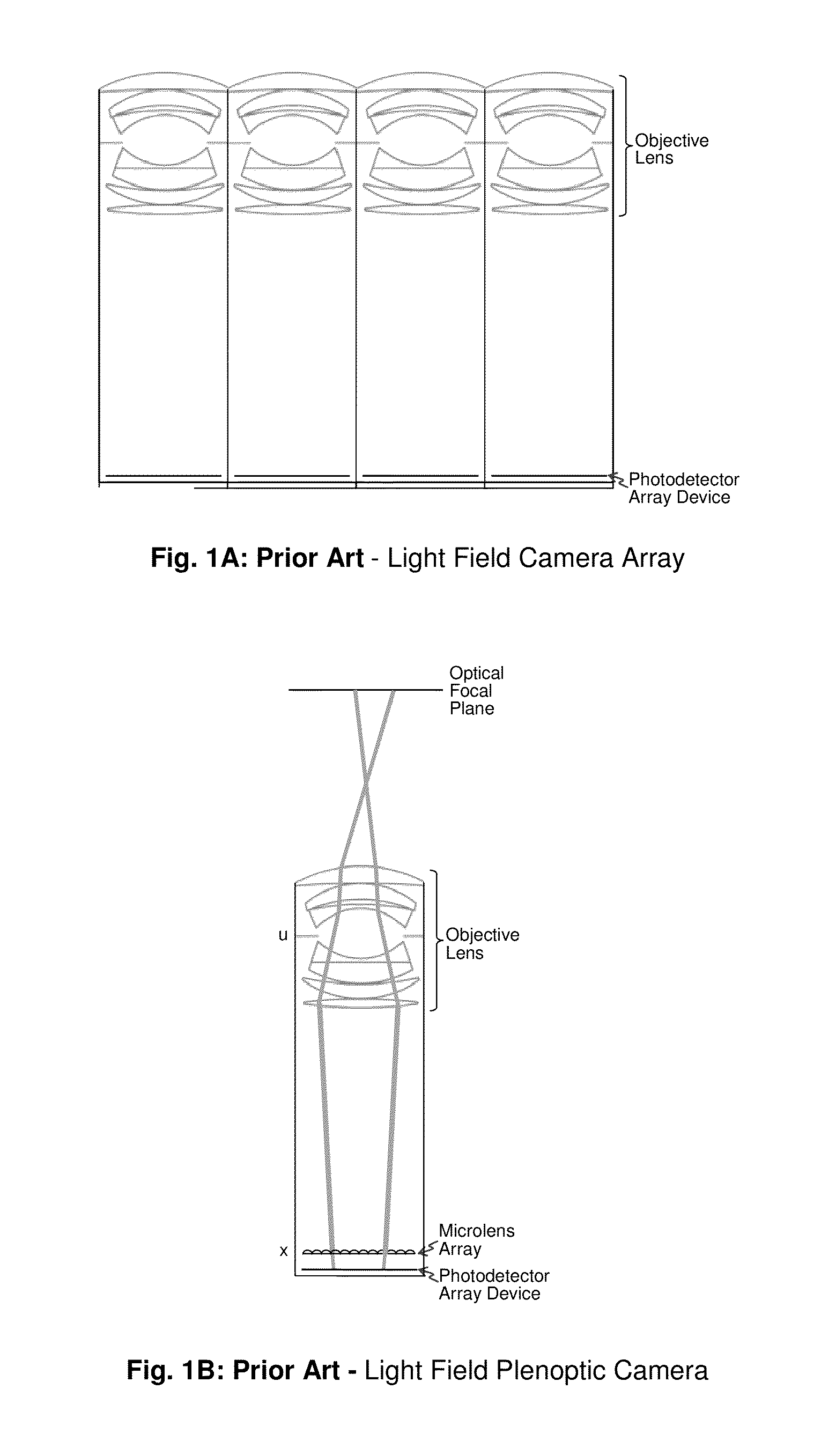
The drawbacks of this approach are rather obvious; in order to capture a reasonable angular extent with each camera in the array, the array of objective lenses will span a much larger area than their photo-detectors and will each have a rather large optical track length, thus making the whole camera array of FIG. 1A be limited in terms of the number of views of the light field it can capture, and excessively bulky, thus not at all suitable for embedding in mobile devices.
Although the plenoptic camera of FIG. 1B would potentially provide a higher number of views of the light field and would also be volumetrically smaller than the camera array of FIG. 1A, the increase in the number of views would be at the expense of reduced spatial resolution.
In addition, similar to the camera array, for the plenoptic camera to cover a reasonable angular extent, it must employ an as large as possible diameter objective lens which in turn requires a large optical track length, thus make the plenoptic camera also bulky and not at all suitable for embedding in mobile devices.
In other words, the improvement in the spatial resolution per view that may be offered by the radiance camera would be at the expense of increased computational resources.
Furthermore, the mask used in the radiance camera will cause light loss that would tend to reduce the capture image signal to noise ratio (SNR).
In addition, similar to the camera array and the plenoptic camera, for the radiance camera to cover a reasonable angular extent, it must employ as large as possible diameter objective lens which in turn requires a large optical track length, thus making the radiance analysis camera also bulky and not at suitable for embedding in mobile devices.
1. The depth of their light field is limited by the focus depth of their objective lens;
2. The field of view of their light field is limited by the angular extent of their objective lens;
3. Their objective lens and MLA (micro lens arrays) must have a matched F#, which results in complicated and costly lens system designs;
4. The large diameter of the objective lens needed to achieve a reasonable size field of view typically results in a rather large optical track length which in turn causes the volumetric size of the light field camera to become large, thus reducing the utility of the camera and preventing its use in mobile applications;
5. The objective lens system adds well known optical distortions and aberrations, such as barrel distortion, TV distortion, etc. . . . , which reduce the optical quality of the captured light field and in turn distort the depth and directional information captured by such cameras; and
6. The light field captured by such cameras usually suffers from under-sampling and resultant sampling artifacts because the limited resolution of the sensor, which typically has to be apportioned between the achievable spatial and angular resolution, limits the total number of directions these light field cameras can capture.

Method used


Image

  • Spatio-temporal light field cameras
  • Spatio-temporal light field cameras
  • Spatio-temporal light field cameras

Examples


embodiment 600

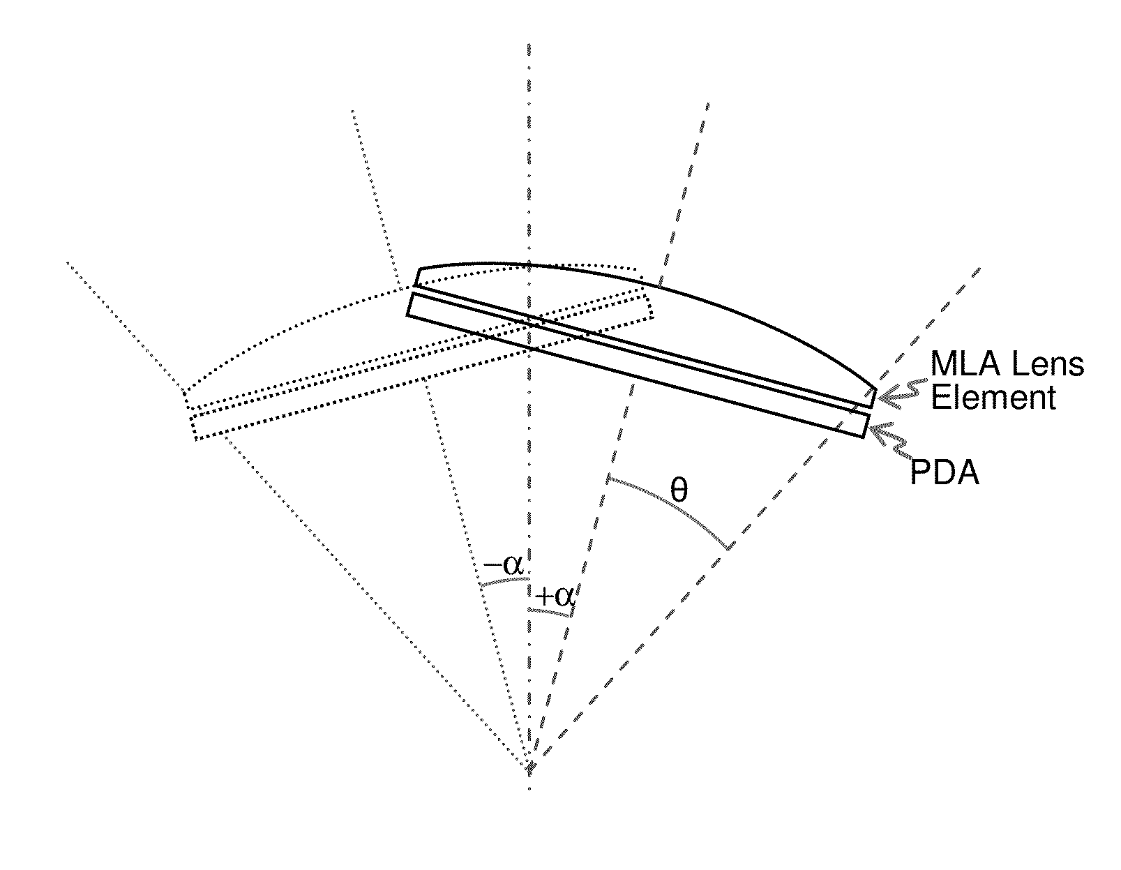
[0054]Referring to the side view illustration of FIG. 6, the articulation of the bonding pad 625 together with the bonded PDA / MLA assembly 230 would be accomplished using a set of electromagnets 635 placed at the four corners of the backside of the hinged bonding pad 625, and a set of permanent magnets 636 placed on the topside of base layer 630 in alignment with the four corners of the backside of the hinged bonding pad 625. The electromagnets 635 would be a coil having a metal core formed at wafer level using multilayer imprint lithography on the backside of the hinged bonding pad 625. The permanent magnets 636 would be a thin magnetic strip typically of neodymium magnet (Nd2Fe14B) or the like. Articulation of the hinged bonding pad 625 together with the bonded PDA / MLA assembly 230 as described earlier would be accomplished by driving the set of electromagnets 635 with an electrical signal having the appropriate temporal amplitude variation to affect the appropriate temporal varia...

embodiment 700

[0057]The hinged pad 721 / 735 is retained in place within the surface curvature of the pedestal 730 / 736 by the spring layer 725 which contains at each of its four corners a single spiral shaped spring 726 that is etched into the spring layer 725. As illustrated in FIG. 7 exploded view isometric, the inner end of each of the four spiral shaped springs incorporates an inner bonding pad 727 which corresponds to an identical bonding pad 722 located at the backside of the pad layer 721. Embedded within the spiral shaped springs 726 are multiple metal rails which are used to route the electrical interface signals from the inner bonding pad 727 to a set of contact pads 728 located at the peripheral edge of the backside of the spring layer 725. The edge contacts 728 on the backside of the outer end of the spring layer 725 correspond to a matching set of bonding pads 729 that are located at the peripheral edge of the base layer 730. The edge contacts on the topside of the base layer 730 are c...


PUM


Abstract

Spatio-temporal light field cameras that can be used to capture the light field within its spatio temporally extended angular extent. Such cameras can be used to record 3D images, 2D images that can be computationally focused, or wide angle panoramic 2D images with relatively high spatial and directional resolutions. The light field cameras can be also be used as 2D / 3D switchable cameras with extended angular extent. The spatio-temporal aspects of the novel light field cameras allow them to capture and digitally record the intensity and color from multiple directional views within a wide angle. The inherent volumetric compactness of the light field cameras make it possible to embed in small mobile devices to capture either 3D images or computationally focusable 2D images. The inherent versatility of these light field cameras makes them suitable for multiple perspective light field capture for 3D movies and video recording applications.

Description

CROSS-REFERENCE TO RELATED APPLICATIONS[0001]This application claims the benefit of U.S. Provisional Patent Application No. 61 / 654,688 filed Jun. 1, 2012.BACKGROUND OF THE INVENTION[0002]1. Field of the Invention[0003]The present invention relates to the field of light field cameras, radiance cameras, directional light capture, 3D cameras and 2D / 3D switchable cameras.[0004]2. Prior Art[0005]The advent of nano-scale semiconductors is making it possible to have sufficient computing resources within a typical mobile device, such as a cell phone or a tablet PC, for example, to process high resolution visual information received and / or transmitted through the high data rate mobile networks such devices can typically connect to. A typical mobile device now has a 1M pixel display and an 8M pixel camera allowing the mobile user to view and capture high resolution visual information. With such visual communication capabilities, mobile devices are on the verge of being capable of processing 3...

Claims


Application Information

Patent Timeline
Patent Type & Authority Patents(United States)
IPC IPC(8): H04N5/225H04N5/232H04N13/02
CPCH04N13/0207H04N5/225H04N5/2254H04N5/23212H04N5/23248H04N13/0285H04N13/207H04N13/282H04N13/286H04N13/289H04N23/957H04N23/00H04N23/661H04N23/67H04N23/68H04N13/236G02B30/27H04N25/48H04N23/16H04N23/45H04N23/54H04N23/57H04N23/80H04N23/90H04N23/667H04N23/815H04N23/951G02B3/0012G02B13/0085G02B27/1066G02B27/1073G02B27/123G06T7/557G02B3/0056G06T2207/10024G06T2207/10028G06T2207/10052H04N5/04
Inventor EL-GHOROURY, HUSSEIN S.ALPASLAN, ZAHIR Y.CAI, JINGBOMAIERS, MARTYWARNER, PHILIPMCNEILL, DALE A.
Owner OSTENDO TECH INC
Learn More