

Suspended liquid hydrogen storage tank
a liquid hydrogen and storage tank technology, applied in the direction of domestic cooling apparatus, container discharge methods, lighting and heating apparatus, etc., can solve the problems of increased bending force on the rods, requiring extra material, and uneven stress distribution inside the rods, so as to facilitate the preloading of suspension members and limit parasitic heat leakage
- Summary
- Abstract
- Description
- Claims
- Application Information
AI Technical Summary
Benefits of technology
Problems solved by technology
Method used
Image

Examples
Embodiment Construction
[0028]The following description of the preferred embodiment is merely exemplary in nature and is in no way intended to limit the invention, its application, or uses.
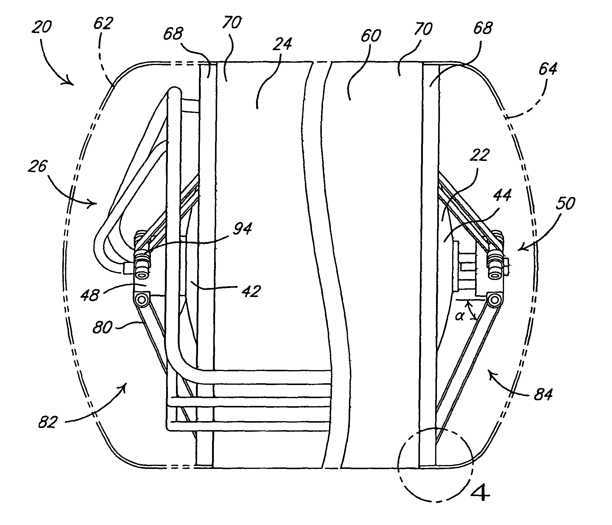
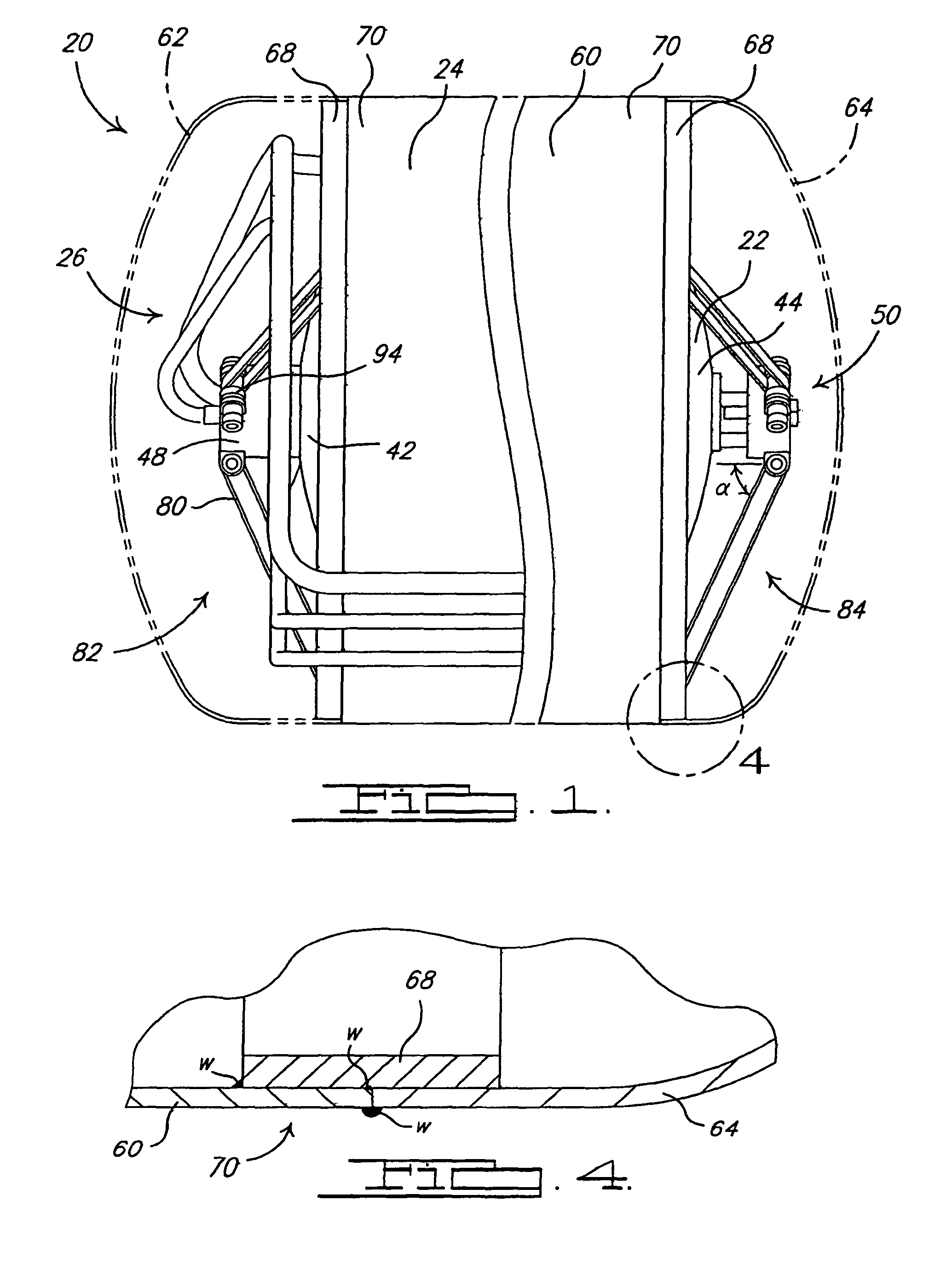
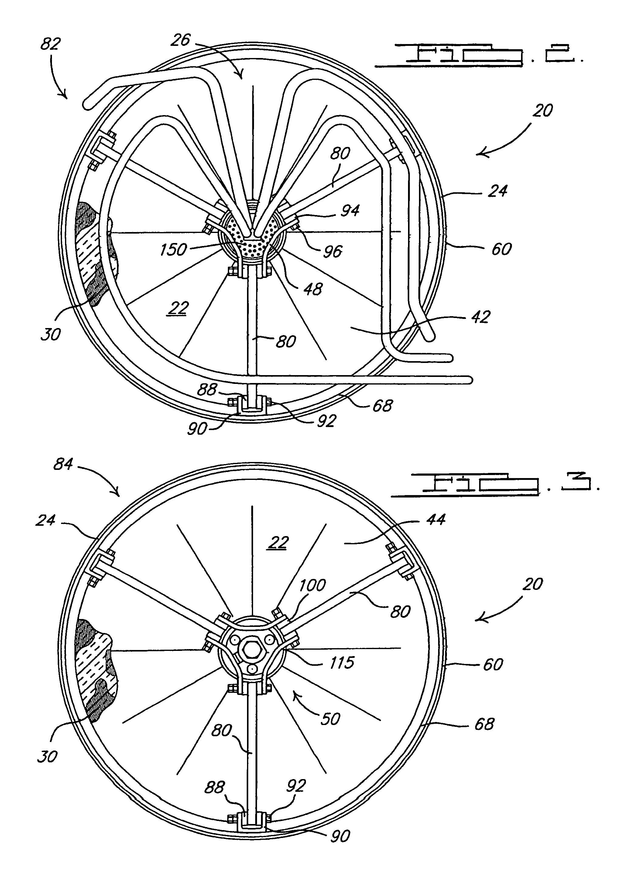
[0029]A cryogenic storage tank 20 according to the principles of the present invention is shown in FIG. 1. Storage tank 20 includes an inner tank / vessel 22 that is suspended within an outer tank / vessel 24 in a spaced relation therefrom. Inner and outer vessels 22, 24 are both fluid-tight vessels. Inner vessel 22 is operable to store a fluid, such as liquid hydrogen, therein at cryogenic temperatures. A plurality of fluid flow lines 26 provide fluid flow paths from an exterior of outer vessel 24 into an interior of inner vessel 22 and enter inner vessel 22 through a common-access tube 28 (FIG. 7A), as described in more detail below. Fluid flow lines 26 allow a fluid to be inserted into and removed from the interior of inner vessel 22. A plurality of insulation layers 30 are wrapped around the exterior of inner vessel 22 i...
PUM
 Abstract
Description
Claims
Application Information