
Suspended liquid hydrogen storage tank

Inactive Publication Date: 2007-03-29
GM GLOBAL TECH OPERATIONS LLC
View PDF5 Cites 13 Cited by
  • Summary
  • Abstract
  • Description
  • Claims
  • Application Information

AI Technical Summary

Benefits of technology

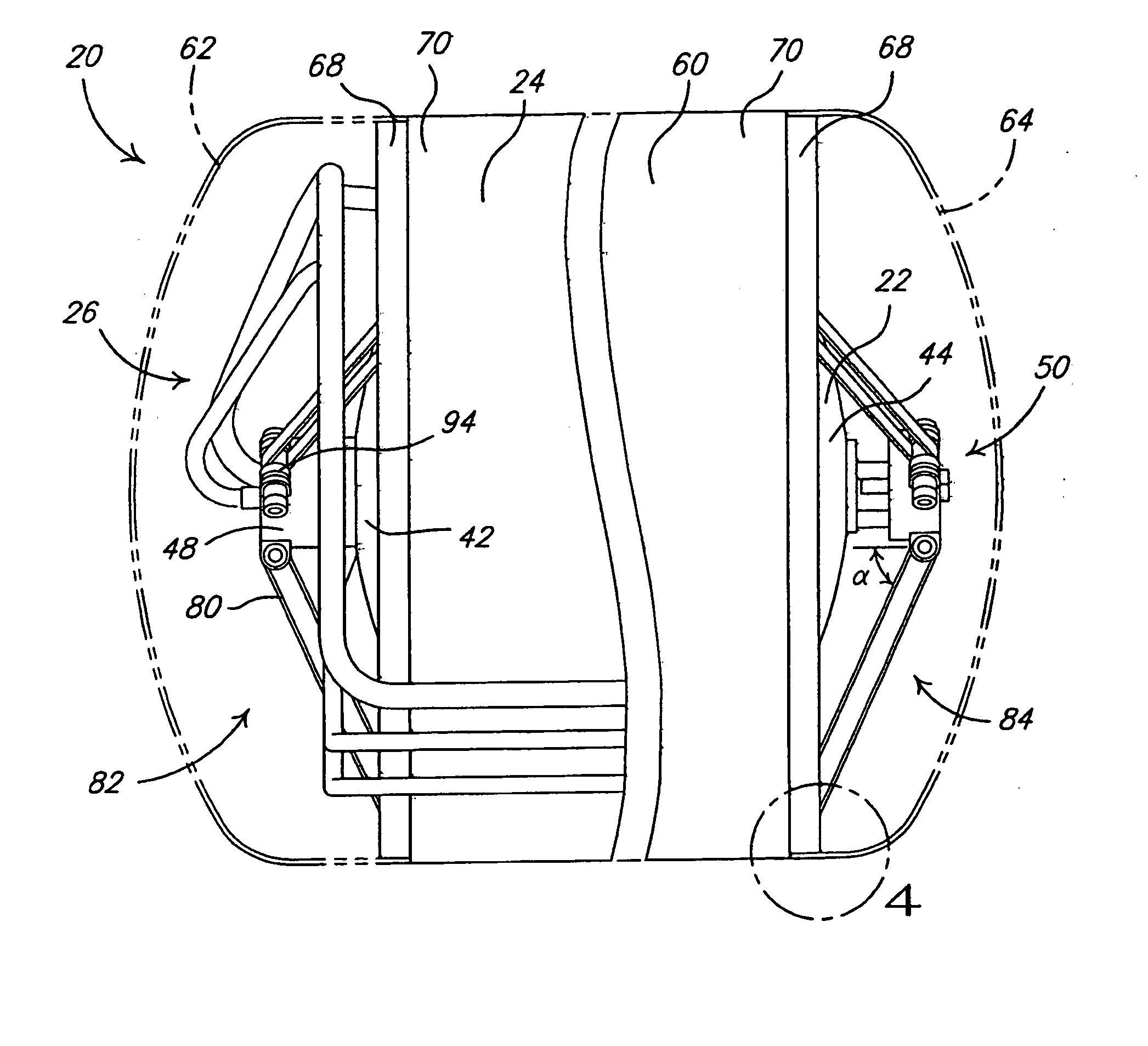
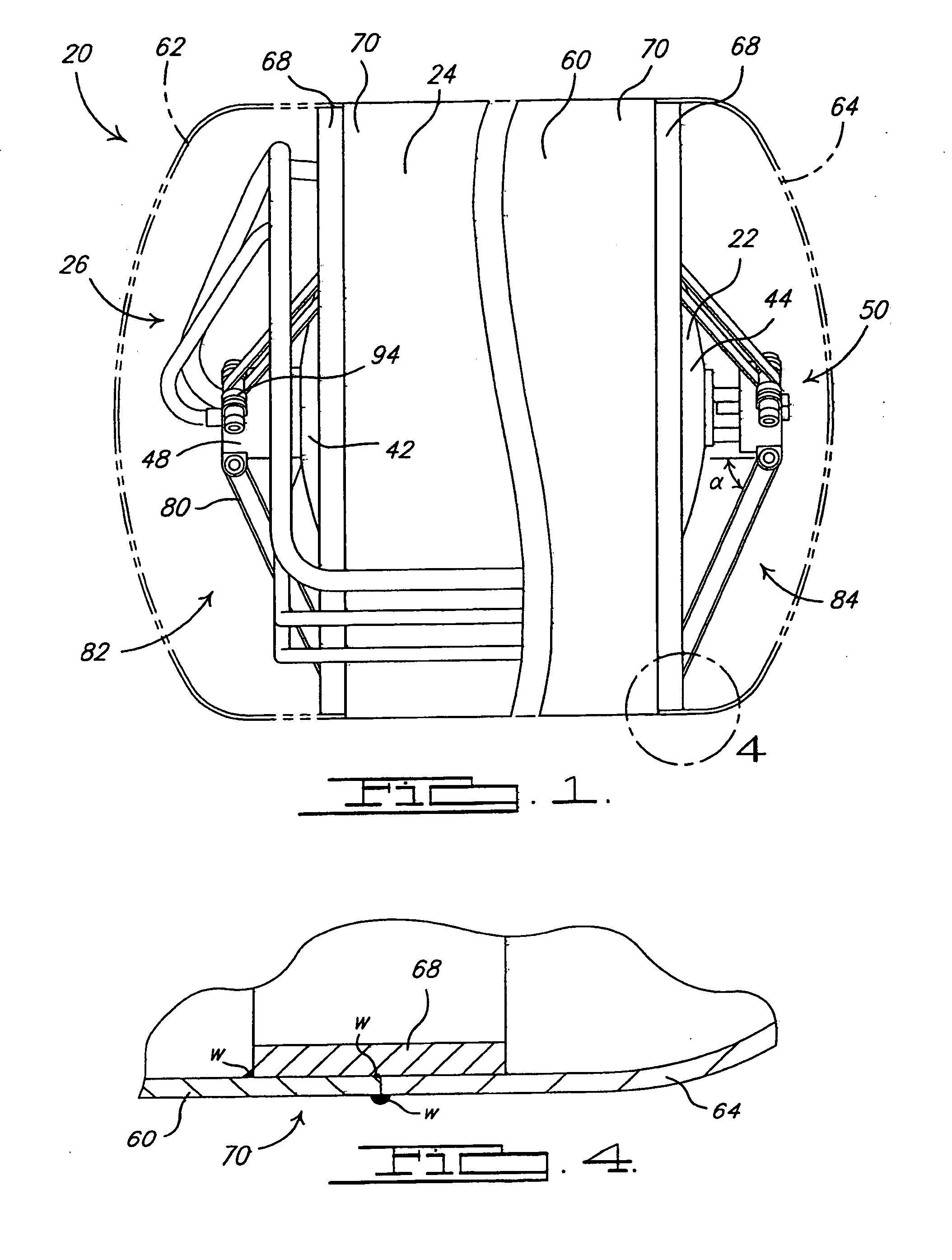
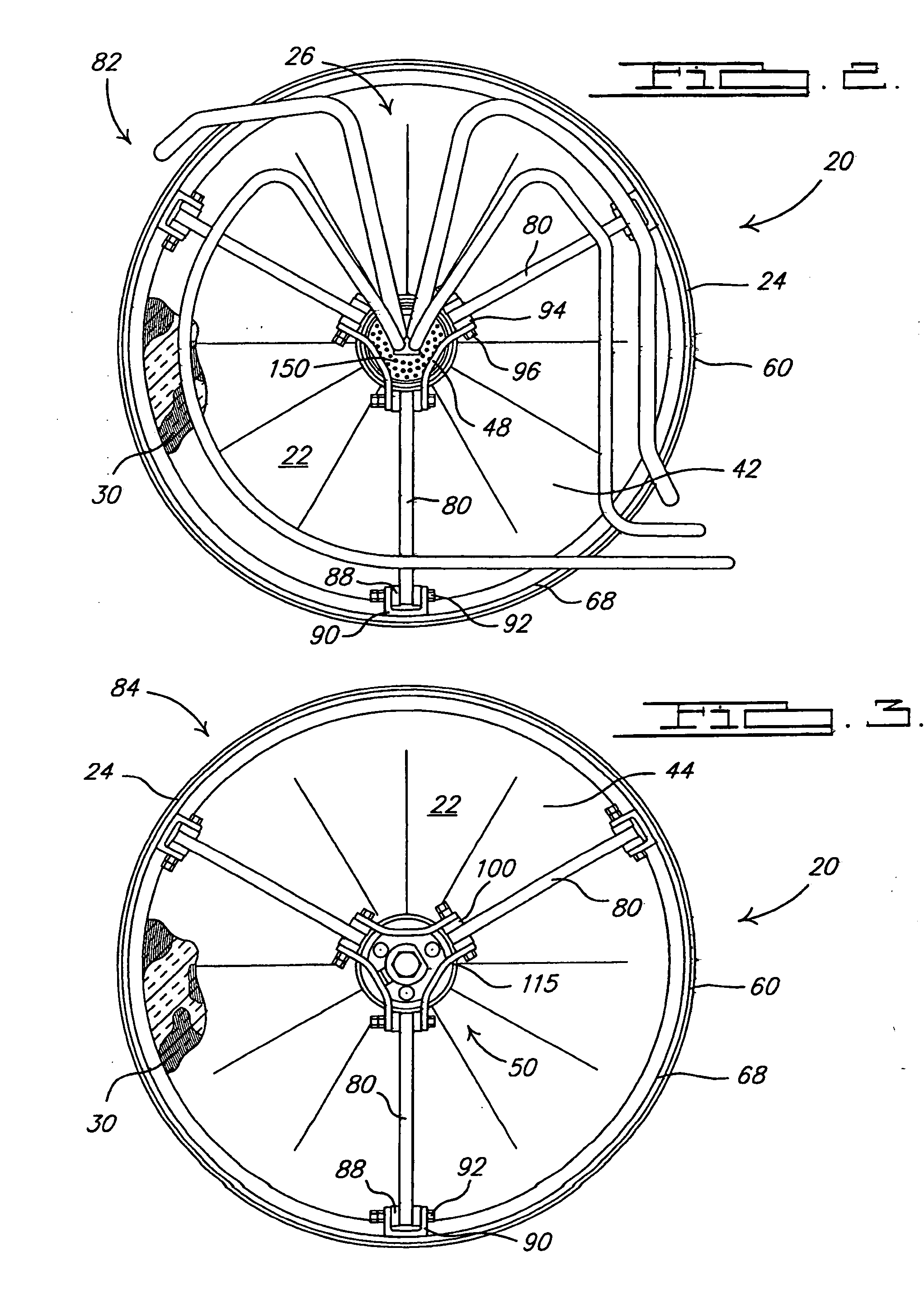
[0007] The present invention provides an apparatus and method for suspending an inner tank within an outer tank to form a cryogenic storage tank. Opposing ends of the inner tank are suspended from the outer tank by suspension members. A preloading device facilitates the preloading of the suspension members to suspend the inner tank within the outer tank. The suspension members constrain the inner tank in a statically determinable manner so that a desired preloading and loading can be imparted upon the suspension members. Furthermore, the suspension members advantageously limit the parasitic heat leaks between the inner and outer tanks.

Problems solved by technology

However, as the rods get longer, the bending force on the rods increases and a larger diameter rod is required to support the load over the longer distance.
Additionally, the stress distribution inside the rods is not homogeneous thus requiring extra material when using rods regardless of the length.
This in turn requires a larger surface area for the contact between the rods and the inner tank which increases the amount of heat being conducted through the rods and the resulting parasitic heat leak.
The use of four rods on each end statically overconstrains the inner tank thereby resulting in an undefined stress distribution due to the preload and when the inner tank is loaded with a fluid.
The extra rods also provide extra parasitic heat leaks.
Additionally, the individual preloading of each rod slows down production of such cryogenic storage tank thus increasing production cost.

Method used


Image

  • Suspended liquid hydrogen storage tank
  • Suspended liquid hydrogen storage tank
  • Suspended liquid hydrogen storage tank

Examples


Embodiment Construction

[0028] The following description of the preferred embodiment is merely exemplary in nature and is in no way intended to limit the invention, its application, or uses.

[0029] A cryogenic storage tank 20 according to the principles of the present invention is shown in FIG. 1. Storage tank 20 includes an inner tank / vessel 22 that is suspended within an outer tank / vessel 24 in a spaced relation therefrom. Inner and outer vessels 22, 24 are both fluid-tight vessels. Inner vessel 22 is operable to store a fluid, such as liquid hydrogen, therein at cryogenic temperatures. A plurality of fluid flow lines 26 provide fluid flow paths from an exterior of outer vessel 24 into an interior of inner vessel 22 and enter inner vessel 22 through a common-access tube 28 (FIG. 7A), as described in more detail below. Fluid flow lines 26 allow a fluid to be inserted into and removed from the interior of inner vessel 22. A plurality of insulation layers 30 are wrapped around the exterior of inner vessel 2...


PUM


Abstract

An apparatus and method for suspending an inner tank within an outer tank to form a cryogenic storage tank. Opposing ends of the inner tank are suspended from the outer tank by suspension members. A preloading device facilitates the preloading of the suspension members to suspend the inner tank within the outer tank. The suspension members constrain the inner tank in a statically determinable manner so that a desired preloading and loading can be imparted upon the suspension members. The suspension members advantageously limit the parasitic heat leaks between the inner and outer tanks.

Description

FIELD OF THE INVENTION [0001] The present invention relates to liquid hydrogen storage and, more particularly to a liquid hydrogen storage tank having an inner tank suspended within an outer tank. BACKGROUND OF THE INVENTION [0002] Typical multi-layered vacuum super insulated cryogenic tanks utilize a pair of cylindrical inner and outer tanks that are arranged concentrically with the inner tank residing in an interior of the outer tank. There are multiple radiant heat shields, approximately 30-80, coiled around the inner tank between the inner and outer tanks. A high vacuum exists between the inner and outer tanks to further prevent heat transfer. This type of thermal insulation is called a multi-layered vacuum super insulation. These storage tanks are capable of storing fluids at cryogenic temperatures. [0003] The inner tank is positioned within the outer tank so that the inner tank does not contact the outer tank and so that thermal conduction paths between the inner and outer tan...

Claims


Application Information

Patent Timeline
IPC IPC(8): F17C13/00
CPCF17C1/00Y02E60/321F17C2201/056F17C2203/011F17C2203/014F17C2203/015F17C2203/016F17C2203/03F17C2203/0391F17C2203/0617F17C2205/0149F17C2205/0361F17C2209/22F17C2209/221F17C2221/012F17C2223/0161F17C2223/033F17C2223/045F17C2223/047F17C2225/0123F17C2227/0323F17C2227/0374F17C2250/0408F17C2260/031F17C2260/033F17C2265/066F17C2270/0168F17C2201/0109Y02E60/32
Inventor IMMEL, RAINERMATOS DA SILVA, JADER
Owner GM GLOBAL TECH OPERATIONS LLC
Learn More