Expandable power distribution unit

a technology of power distribution unit and expansion plate, which is applied in the direction of connection contact material, electrical apparatus casing/cabinet/drawer, coupling device connection, etc., and can solve problems such as the problems of known manufactured wiring system

Inactive Publication Date: 2010-07-20
COMMSCOPE TECH LLC
View PDF11 Cites 191 Cited by
  • Summary
  • Abstract
  • Description
  • Claims
  • Application Information

AI Technical Summary

Problems solved by technology

Known manufactured wiring systems are not without problems.

Method used


Image

  • Expandable power distribution unit
  • Expandable power distribution unit
  • Expandable power distribution unit

Examples


Embodiment Construction

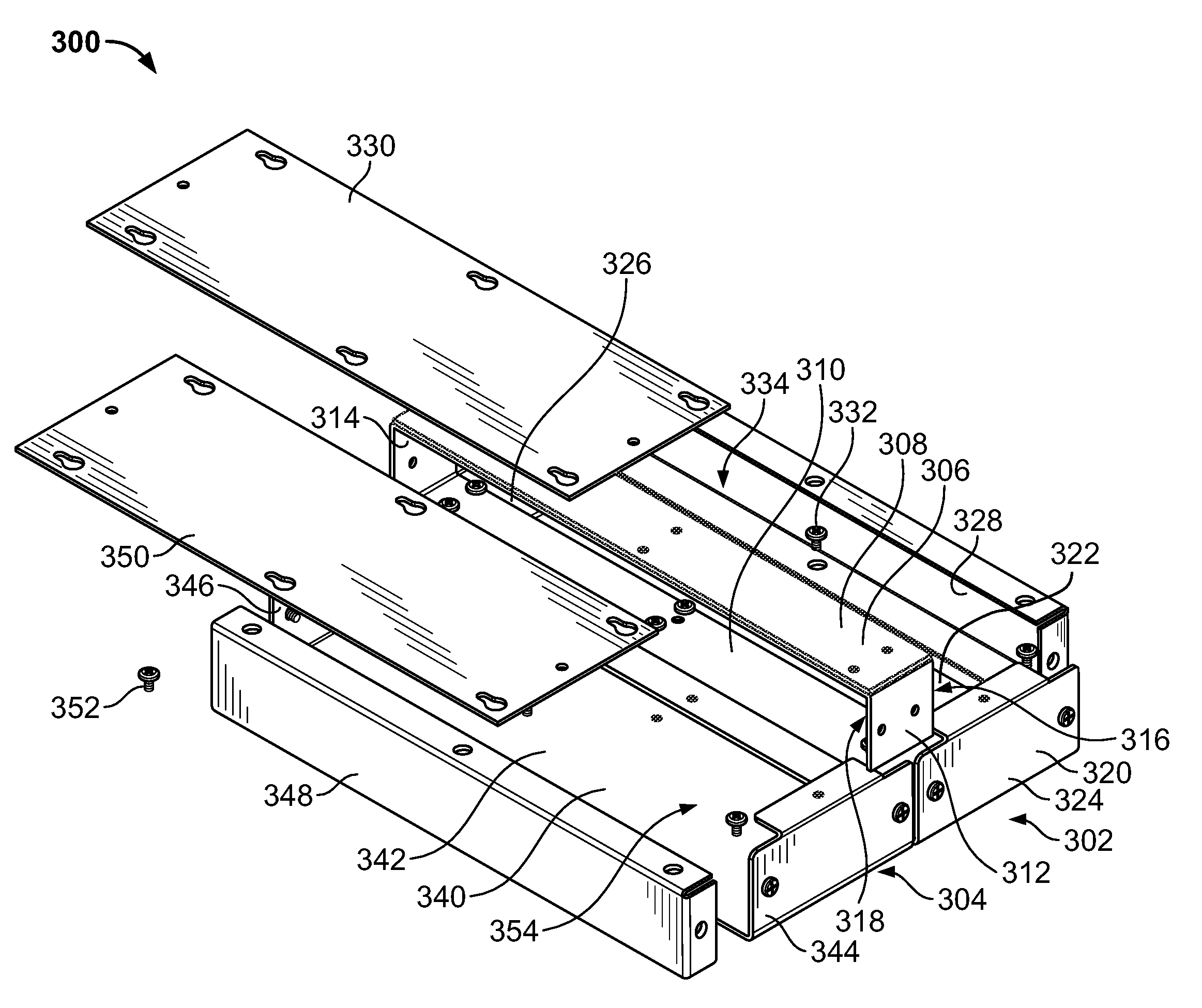
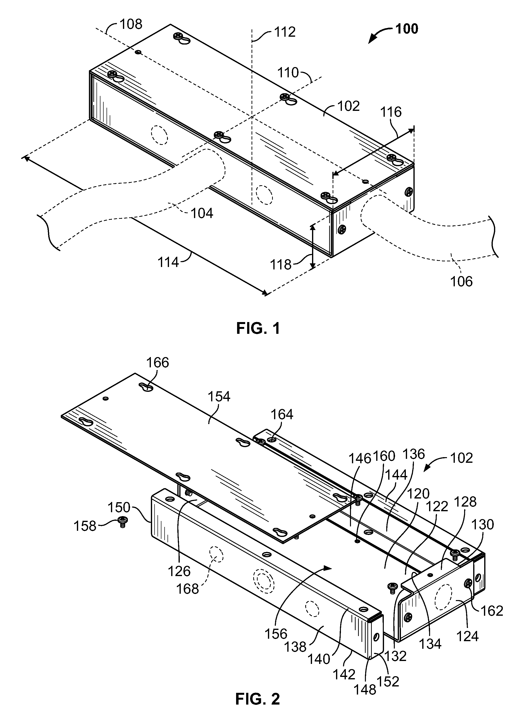
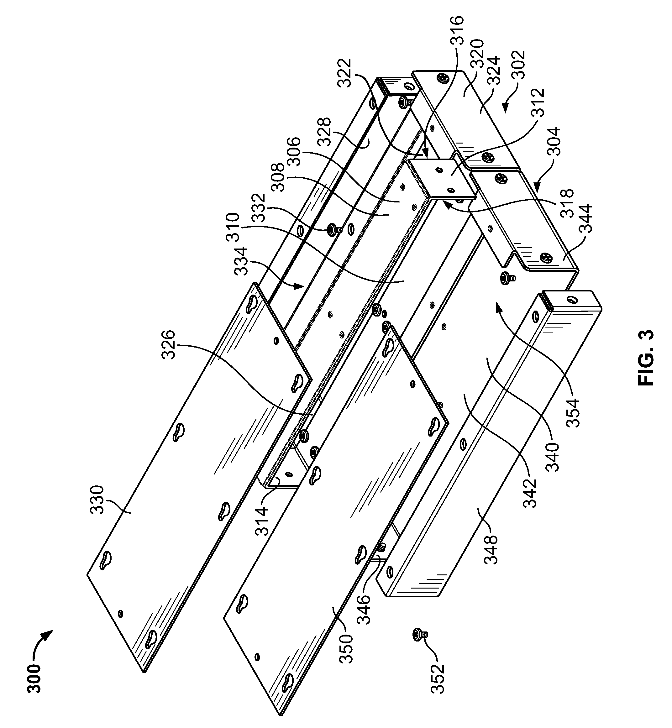
[0019]FIG. 1 is a top perspective view of a power distribution unit 100 having one power box 102 formed in accordance with an exemplary embodiment. The power distribution unit 100 forms part of a manufactured wiring system. In an exemplary embodiment, the power distribution unit 100 is configured to distribute power from one power system to a different power system. For example, the power distribution unit 100 is configured to distribute power from a building power system to a manufactured wiring system. In the illustrated embodiment, the power distribution unit 100 receives power from a first conduit 104, which is represented schematically in FIG. 1, and transfers the power to a second conduit 106, which is also represented schematically in FIG. 1. Wire(s) of the conduits 104, 106 are electrically connected to one another within the power box 102. The wires may be electrically connected either directly or indirectly.

[0020]In the illustrated embodiment, the power box 102 is a polyhe...


PUM


Abstract

A power distribution unit includes a first power box including a first chamber having a first termination zone, wherein a first wire set from a supply conduit is configured to be terminated at the first termination zone. The power distribution unit also includes a second power box ganged together with the first power box. The second power box has a second chamber open to the first chamber, and the second chamber has a second termination zone. A second wire set from at least one of the supply conduit and the first termination zone is configured to be terminated at the second termination zone.

Description

BACKGROUND OF THE INVENTION[0001]The subject matter herein relates generally to power distribution units, and more particularly to power distribution units having a plurality of power boxes ganged together.[0002]Modular or manufactured wiring systems are known and in use today. Typical applications for manufactured wiring systems include modular office systems and raised floor systems. Modular office systems employ prefabricated modular wall units which are joined together in various configurations to divide a workspace into smaller offices or work areas. Such modular wall panels are typically equipped with raceways, for example along a bottom edge of the modular panels, for housing electrical cabling and electrical components such as power distribution units, junction boxes, power converters, and data network boxes for distributing power and / or data throughout the workspace. Raised floor systems employ floor panels that are elevated above a sub-floor and that provide voids for the ...

Claims


Application Information

Patent Timeline
Patent Type & Authority Patents(United States)
IPC IPC(8): H01J5/00
CPCH02G3/086H02G3/185
Inventor JONES, SARAH JEANLINCOLN, III, CLIFFORD FRANKLIN
Owner COMMSCOPE TECH LLC
Why Eureka
Try Eureka