Toner dispensing system and method for controlling the same

a technology of toner and dispensing system, applied in the direction of instruments, electrographic process equipment, optics, etc., can solve the problems of inaccurate estimation method using only pixel count, inability to describe different types of images, and inability to disclose an algorithm that uses, etc., to achieve accurate toner consumption monitoring

Inactive Publication Date: 2010-07-20
S PRINTING SOLUTION CO LTD
View PDF6 Cites 14 Cited by
  • Summary
  • Abstract
  • Description
  • Claims
  • Application Information

AI Technical Summary

Benefits of technology

[0012]It is another aspect of the invention to provide a toner dispensing system and a method for controlling the same, which provide accurate toner consumption monitoring, to provide accurate information on the remaining and used amounts of toner, during an electrophotographic printing process.

Problems solved by technology

However, when only the pixel count is used, it is not possible to describe different types of images, such as text / line, halftone, and solid area images, for which different amounts of toner are consumed.
Thus, the estimation method using only the pixel count is inaccurate.
However, U.S. Pat. No. 6,374,064 does not disclose an algorithm that uses transition and pixel counts, in the dispensing system, to replenish the toner consumed in the dual component development system.
Without considering the job length, the dispensing system may fail to accurately determine the amount of toner to be dispensed to replenish consumed toner.

Method used


Image

  • Toner dispensing system and method for controlling the same
  • Toner dispensing system and method for controlling the same
  • Toner dispensing system and method for controlling the same

Examples


Embodiment Construction

[0024]Reference will now be made in detail to various embodiments of the present invention, examples of which are illustrated in the accompanying drawings, wherein like reference numerals refer to the like elements throughout. The embodiments are described below in order to explain the present invention by referring to the figures.

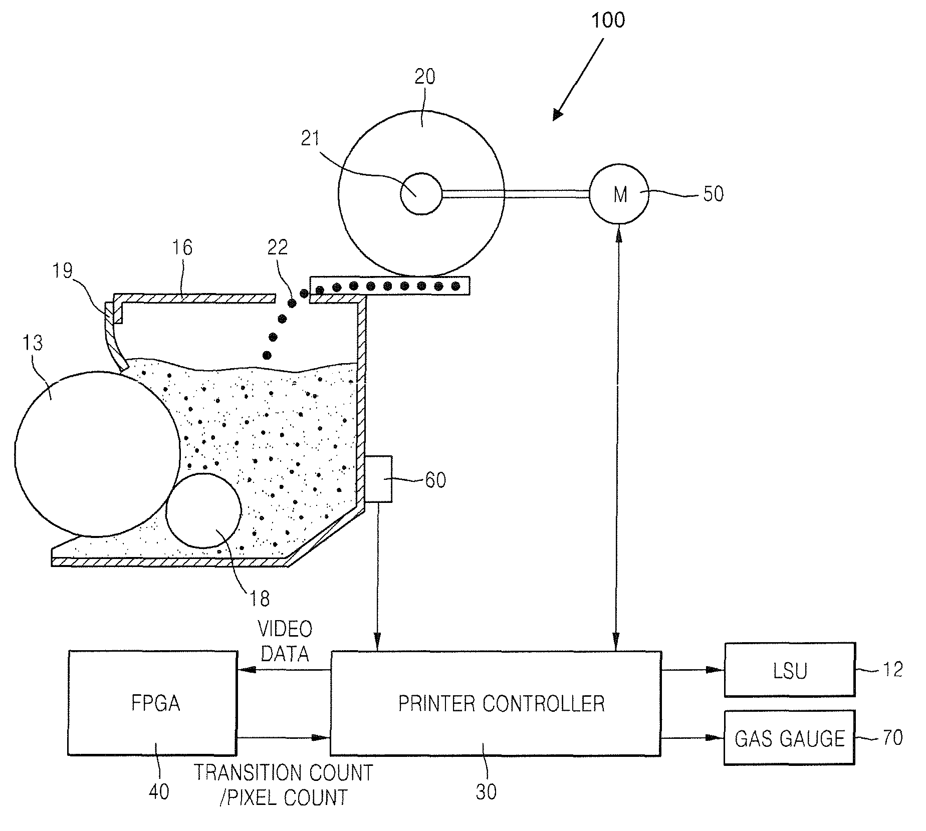
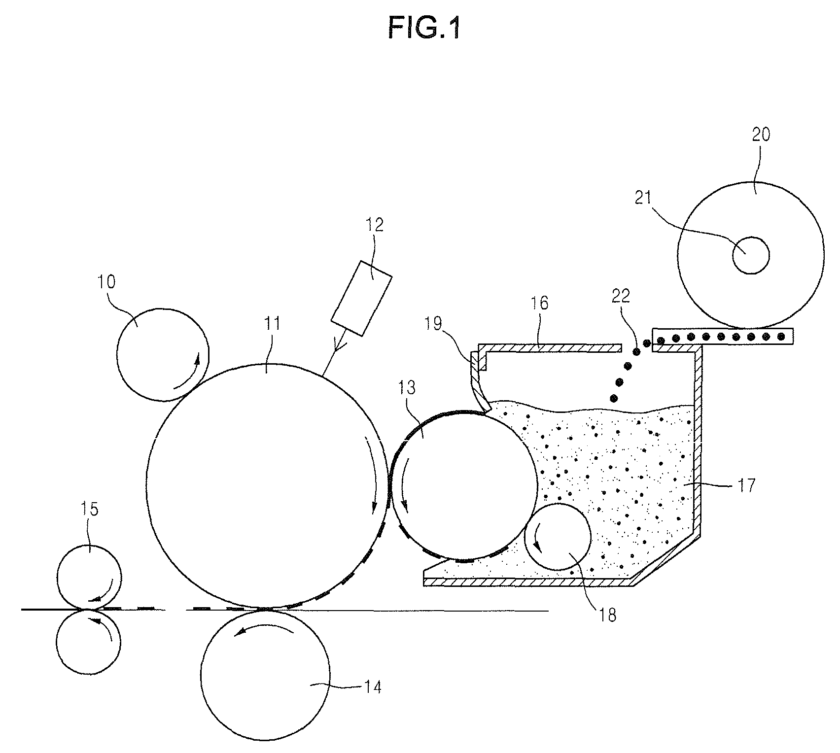
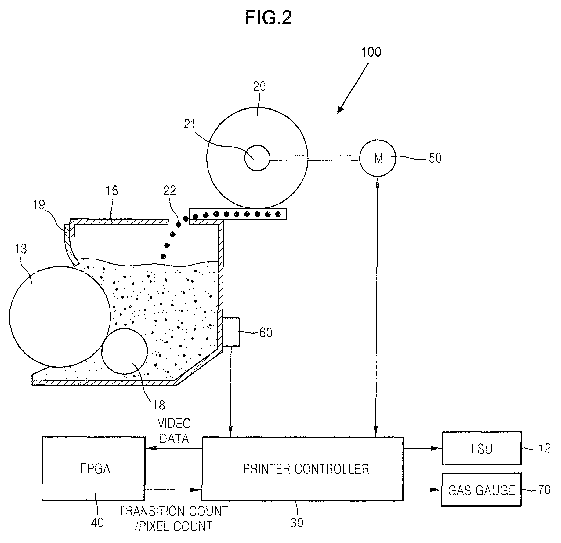
[0025]FIG. 1 illustrates basic elements of an image forming apparatus, according to an example embodiment of the present teachings. In an electrophotographic printing process, first, a charge roller 10 charges a photoreceptor 11. A corotron / scorotron may be used instead of the charge roller 10.

[0026]A laser scanner unit 12 selectively discharges the photoreceptor 10 in a pattern corresponding to an image to be printed. A raster outer scanner (ROS) may be used instead of the laser scanner unit 12.

[0027]The laser scanner unit 12 generally includes a laser source and a revolutionary polygon mirror (not shown) and discharges specific portions of the charged ph...


PUM


Abstract

A toner dispensing system and a method for controlling the same. A toner dispensing amount is determined using a pixel dispensing time related to a pixel count adjusted according to the ratio of a transition count to a pixel count per page, a Δ automatic concentration control dispensing time relating to the difference between the toner concentration of a developer material and target concentration, and a dispensing rate corresponding to a print job length. The determined amount of toner is dispensed into a developer housing. This method can maintain a toner concentration in order to obtain an accurate image density. A remaining toner ratio (%) determined from a total dispensing time, a dispensing rate, and a toner capacity can also be displayed so that the user can monitor the remaining amount of toner, the used amount of toner, etc., during the life of the toner cartridge.

Description

CROSS-REFERENCE TO RELATED APPLICATION[0001]This application claims the benefit of Korean Application No. 2006-122539, filed Dec. 5, 2006, in the Korean Intellectual Property Office, the disclosure of which is incorporated herein by reference.BACKGROUND OF THE INVENTION[0002]1. Field of the Invention[0003]Aspects of the present invention relate to a toner dispensing system, and a method for controlling the same.[0004]2. Description of the Related Art[0005]In a general electrophotographic printing process of an image forming apparatus, for example, a printer, a photocopier, a facsimile machine, or a multi-functional product, a photoreceptor (i.e. a photosensitive drum) is electrically charged, and is then exposed to a light pattern corresponding to an original image, whereby the surface of the photoreceptor is selectively discharged to form a latent image. After the latent image is recorded on the photoreceptor, developer material is applied to the photoreceptor to develop the latent...

Claims


Application Information

Patent Timeline
Patent Type & Authority Patents(United States)
IPC IPC(8): G03G15/08
CPCG03G15/0822G03G15/556G03G15/553G03G2215/0685G03G15/06
Inventor WONG, KAISER
Owner S PRINTING SOLUTION CO LTD
Why Eureka
Try Eureka