

Magnetic tape and magnetic tape device
a magnetic tape and tape body technology, applied in the direction of maintaining the head carrier alignment, the alignment of tracks following on tapes, instruments, etc., can solve the problems of difficult to correctly align the magnetic head, errors may easily occur at the time of recording and/or reproduction, etc., and achieve the effect of high surface smoothness
- Summary
- Abstract
- Description
- Claims
- Application Information
AI Technical Summary
Benefits of technology
Problems solved by technology
Method used
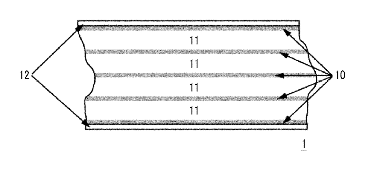
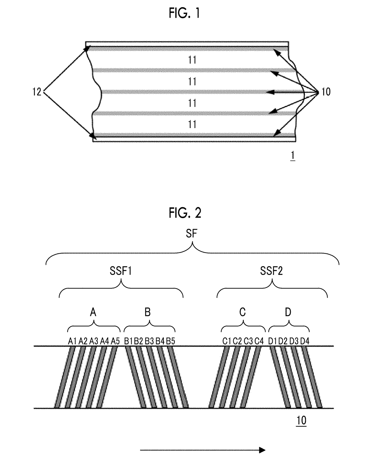
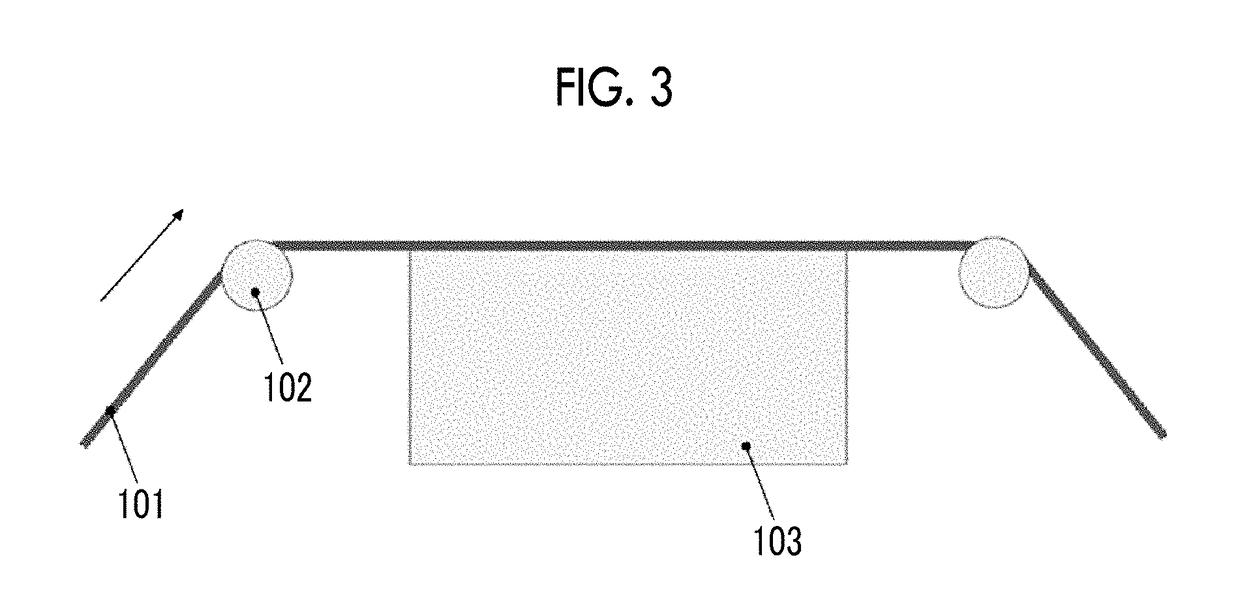
Image

Examples
example 1
[0148]Magnetic Layer Forming Composition
[0149]Magnetic Solution
[0150]Ferromagnetic hexagonal ferrite powder: 100.0 parts
[0151](coercivity Hc: 2100 Oe (168 kA / m), average particle size: 25 nm)
[0152]Sulfonic acid group-containing polyurethane resin: 15.0 parts
[0153]Cyclohexanone: 150.0 parts
[0154]Methyl ethyl ketone: 150.0 parts
[0155]Abrasive Liquid
[0156]α-alumina (average particle size of 110 nm): 9.0 parts
[0157]Vinyl chloride copolymer: (MR110 manufactured by Zeon Corporation): 0.7 parts
[0158]Cyclohexanone: 20.0 parts
[0159]Silica Sol
[0160]Colloidal silica prepared by a sol-gel method (average particle size: 120 nm): 3.5 parts
[0161]Methyl ethyl ketone: 8.2 parts
[0162]Other Components
[0163]Butyl stearate: 1.0 part
[0164]Stearic acid: 1.0 part
[0165]Polyisocyanate (CORONATE manufactured by Nippon Polyurethane Industry): 2.5 parts
[0166]Finishing Additive Solvent
[0167]Cyclohexanone: 180.0 parts
[0168]Methyl ethyl ketone: 180.0 parts
[0169]Non-Magnetic Layer Forming Composition
[0170]Non-magne...
PUM
| Property | Measurement | Unit |
|---|---|---|
| total thickness | aaaaa | aaaaa |
| surface roughness Ra | aaaaa | aaaaa |
| surface roughness Ra | aaaaa | aaaaa |
Abstract
Description
Claims
Application Information