Medical implant device with RFID tag and method of identification of device

Inactive Publication Date: 2005-11-10
DATA TRACE PUBLISHING +1
View PDF10 Cites 109 Cited by
  • Summary
  • Abstract
  • Description
  • Claims
  • Application Information

AI Technical Summary

Benefits of technology

[0022] It is also an object of the invention to utilize radiofrequency identification (RFID) tags on medical implants to prevent counterfeiting of the implants or reusing the same in other patients.
[0023] I

Problems solved by technology

Radiofrequency identification tags (R

Method used


Image

  • Medical implant device with RFID tag and method of identification of device
  • Medical implant device with RFID tag and method of identification of device
  • Medical implant device with RFID tag and method of identification of device

Examples


Embodiment Construction

[0029] While the present invention is susceptible of embodiment in various forms as is shown in the drawings, and will hereinafter be described, a presently preferred embodiment, with the understanding that the present disclosure is to be considered as an exemplification of the invention, and is not intended to limit the invention to the specific embodiments disclosed herein.

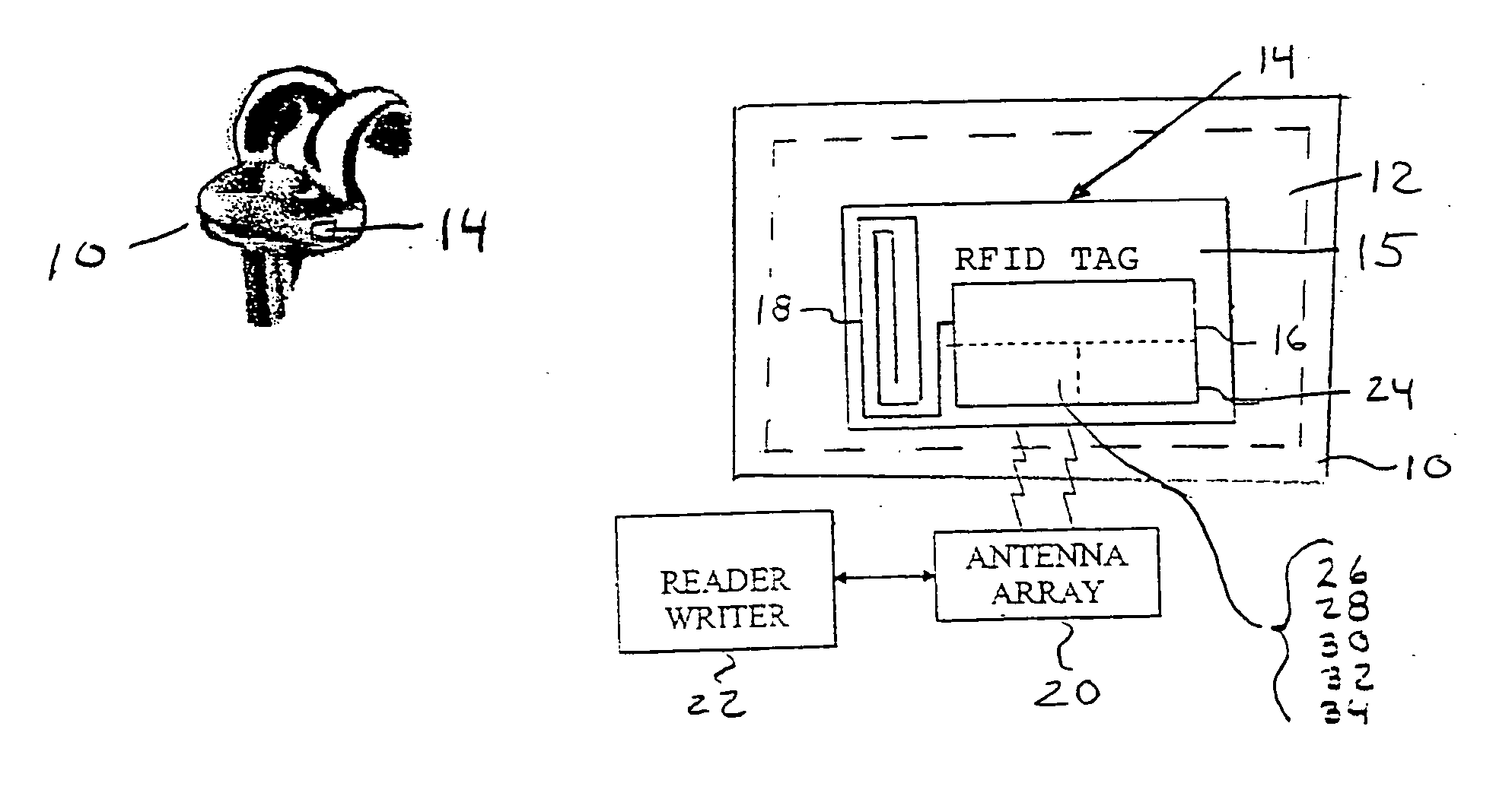
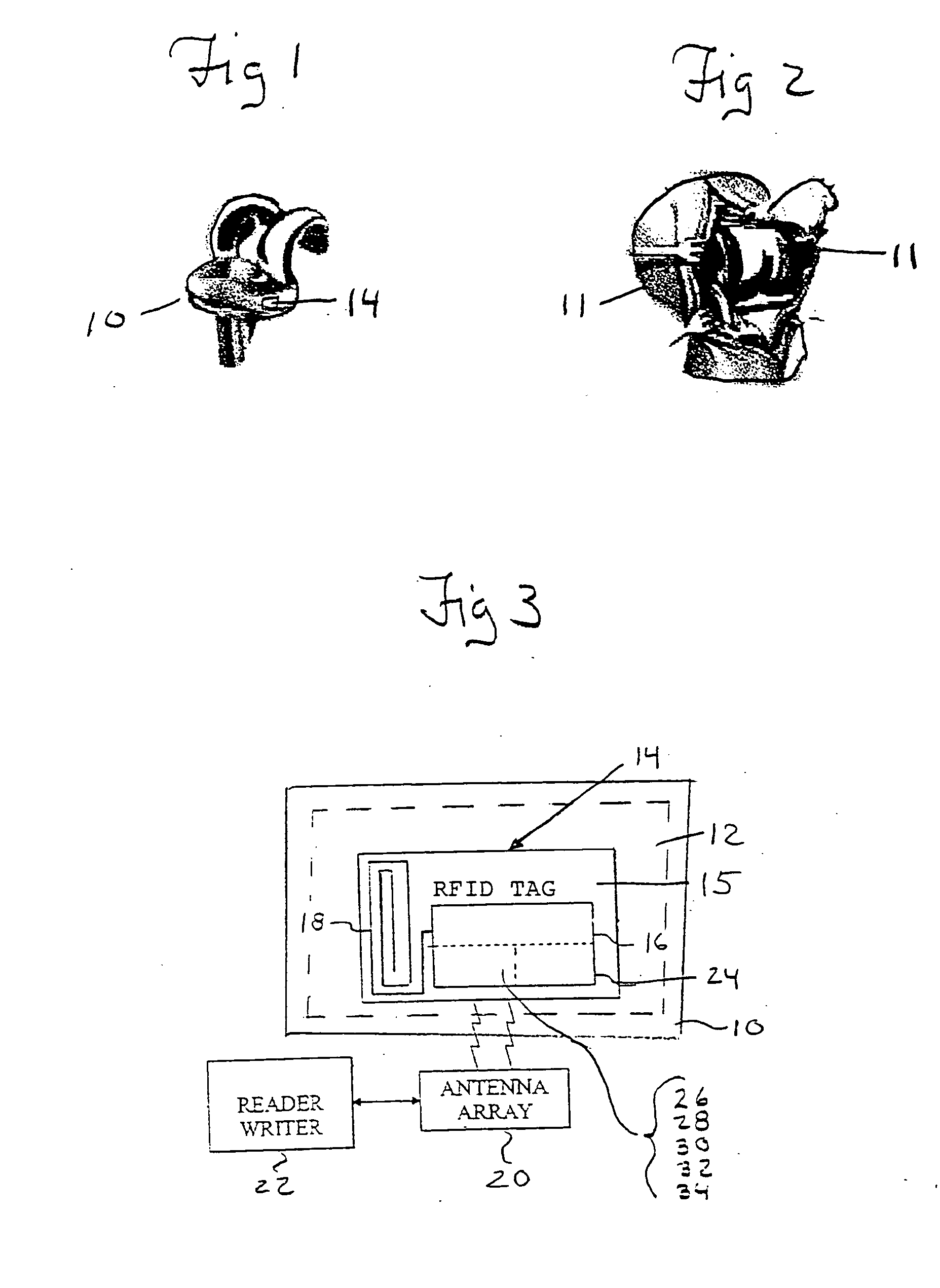
[0030] The present invention is directed to a medical implant with an associated RFID tag and a method of making an interactive medical implant which is sealed against liquid engagement with a radio frequency identification integrated circuit and associated antenna disposed on or within the implant. It is envisioned that the medical implants which will be used are those implants currently used in orthopaedics and cardiac procedures. Orthopaedic implants can consist of implants for joint replacement, implants for hip replacement, implants for knee replacement, implantable spinal cages, implantable spinal plates,...


PUM


Abstract

The present invention is generally directed a method of making an interactive medical implant device including a radio frequency identification tag mounted to said implant covered with a liquid impermeable seal. Identification of the RFID tag with a relevant instrument or patient database allows the physician access to pertinent information regarding the medical implant device.

Description

RELATED APPLICATIONS [0001] There is no related application. FIELD OF INVENTION [0002] The present invention relates generally to a method of determining the manufacturer and model of a medical implant device after implantation and to construction of a medical implant device employing an RFID tag on a surface of the medical implant. BACKGROUND OF THE INVENTION [0003] Radiofrequency identification (RFID) is a type of automatic identification technology that uses low wattage radio frequency transmission for identification and data cataloguing. Radiofrequency identification (RFID) accelerates and facilitates the collection of data and eliminates the need for human operations in the process. Radiofrequency identification (RFID) uses a reader and antenna array which generates an EM-field from 850 MHz and 2 GHz and special tags which respond to the EM-field with the emission of data are attached or embedded to an object. There are no moving parts in radiofrequency identification (RFID) ta...

Claims


Application Information

Patent Timeline
IPC IPC(8): A61B5/00A61B17/68A61B19/00A61N1/08
CPCA61B5/0031A61B5/4528A61B17/68A61N1/08A61B2019/448A61B2560/0219A61B2562/08A61B19/44A61B90/90A61B90/98
Inventor BERGER, J. LEE
Owner DATA TRACE PUBLISHING
Why Eureka
Try Eureka