Mounting structure with a frame-shaped construction

a technology of mounting structure and frame, which is applied in the direction of superstructure subunits, monocoque constructions, vehicle bodies, etc., can solve the problems of reducing the theoretically possible heat transfer surface and insufficient stiffness, and achieves the reduction of the loss of efficiency at the radiator component, the increase of the effect of increasing the moment of inertia and strength

Inactive Publication Date: 2010-08-03
HBPO
View PDF17 Cites 16 Cited by
  • Summary
  • Abstract
  • Description
  • Claims
  • Application Information

AI Technical Summary

Benefits of technology

[0006]It is, therefore, one objective of the invention to create amounting structure whose upper crossmember as the lock crossmember exhibits a great moment of inertia and reduces the air cooled pass-through area only to a negligible extent.
[0007]This objective is achieved by a mounting structure having an increased moment of inertia and strength wherein the moment of inertia can be increased significantly in the upper region of the mounting structure through a lattice structure that is located adjacent to the lower side of the upper crossmember and that can also be referred to as a lattice support frame with truss framework character. In this manner, the upper crossmember of the mounting structure is divided into an upper closed part that ends with the sealing rib, and a lower part that exhibits a high portion of open flow-through area that can be used for the pass-through of the cooling air. For example, the region of the upper crossmember of the mounting structure with the lattice structure can be arranged with its full area in front of one of the radiator components, whereby the lattice structure is designed such that the loss of efficiency that occurs at this radiator component is negligible.

Problems solved by technology

The problem in this situation is that a sufficient stiffness of the crossmember with simultaneously desired weight reduction can be achieved only through a greater construction height in the main load direction.
Especially in cases where a center brace for supporting the upper crossmember at the lower crossmember is to be avoided, the resultant construction height of the crossmember even with favorable profile shapes is such that it leads to covering of the upper parts of the radiator components and in so doing reduces the theoretically possible heat transfer surface.

Method used


Image

  • Mounting structure with a frame-shaped construction
  • Mounting structure with a frame-shaped construction
  • Mounting structure with a frame-shaped construction

Examples


Embodiment Construction

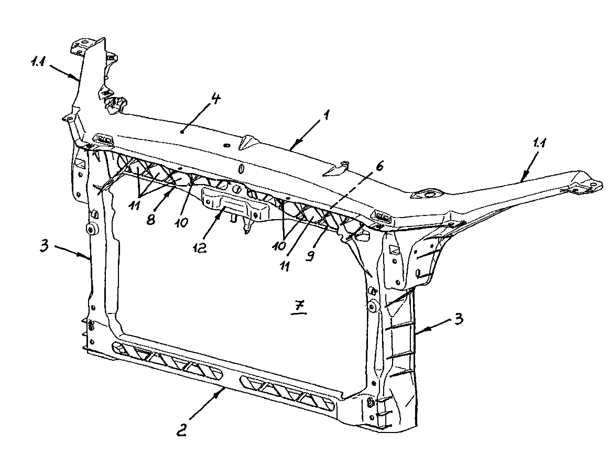
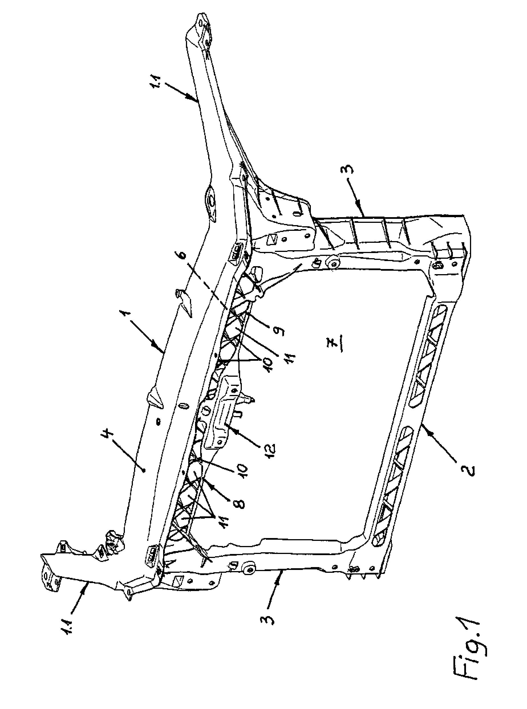
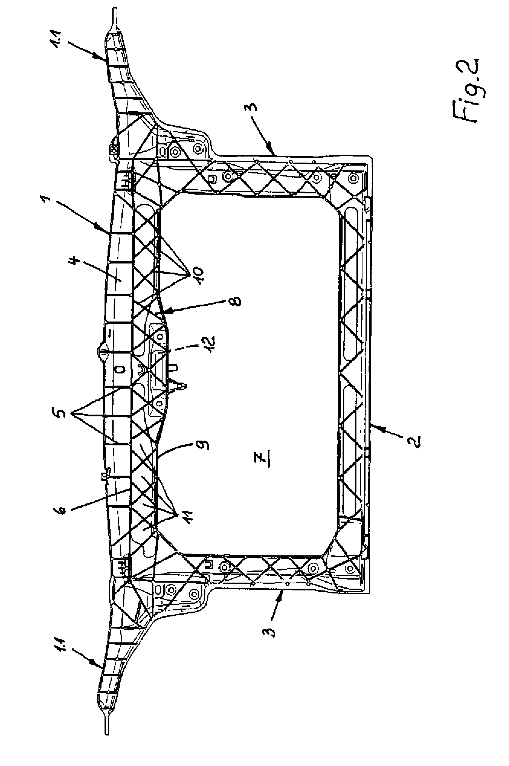
[0011]In detail, the mounting structure shown in the drawing includes an upper crossmember 1, a lower crossmember 2 and sidemembers 3 that connect the upper crossmember 1 to the lower crossmember 2 with one piece. As a result, the mounting structure has the basic structure of an essentially rectangular frame, whereby mounting arms 1.1 protrude from the two upper frame corners at an angle toward the back from which the upper crossmember 1 proceeds.

[0012]The upper crossmember 1 is a profile carrier exhibiting a U-shaped or C-shaped cross-section with its open side being located at the rear side of the mounting structure. In the direction of the front side of the mounting structure, the upper crossmember 1 is provided with a closed wall 4 with bracing bars 5 extending from its rear side in the hollow profile of the upper crossmember 1. The crossmember can be designed as a fully synthetic component, in the preferred design it is a hybrid component of bracing components made of a rigid m...


PUM


Abstract

A mounting structure for the front end of a car or small truck has a frame-shaped structure that surrounds an air cooled pass-through area and exhibits an upper crossmember, a lower crossmember and sidemembers connecting them. The upper crossmember is designed as a closed wall for receiving a hood lock and forms a sealing rib that borders on the air cooled pass-through area for an air-blocking connection of a radiator component. To provide the upper crossmember as the lock crossmember at the mounting structure with a high moment of inertia and to reduce the air cooled pass-through area only to a negligible degree, the upper crossmember is strutted using a lattice structure that is adjacent to the sealing rib and protrudes into the air cooled pass-through area, where the lattice openings form a part of the air cooled pass-through area with their entire opening area.

Description

TECHNICAL FIELD[0001]The invention relates to a mounting structure or frame for frontend modules of passenger cars and small trucks.BACKGROUND INFORMATION[0002]Passenger cars and small trucks generally include a front end mounting structure which serves as the central installation platform for a frontend module of passenger cars or small trucks onto which the various individual components of the frontend module are attached in a preassembly step. Because motor vehicles of the kind included here have similar support structures, frame-shaped mounting structures are used throughout and assume air guiding and air sealing functions for the necessary radiator components. This is accomplished with the sealing rib located at the crossmember of the mounting structure and adjacent to the air cooled pass-through area surrounded by the mounting structure.[0003]In most cases, the upper crossmember of the mounting structure is designed for receiving the hood lock of the respective motor vehicle, ...

Claims


Application Information

Patent Timeline
Patent Type & Authority Patents(United States)
IPC IPC(8): B62D25/08B60R99/00
CPCB62D25/084B62D29/004B62D29/041B62D29/001B62D25/08
Inventor HEMMERSMEIER, RALF
Owner HBPO
Why Eureka
Try Eureka