AI technical title is built by Patsnap AI team. It summarizes the technical point description of the patent document.
a technology of stents and stents, applied in the field of intravascular stents, can solve the problems of poor vessel coverage of flexible current stents, tissue prolapse, rough surface modulation, etc., and achieve the best possible flexibility and conformability, excellent radial strength and radiopacity, and optimal metal fraction
Inactive Publication Date: 2010-08-03
BOSTON SCI SCIMED INC
View PDF253 Cites 19 Cited by
Summary
Abstract
Description
Claims
Application Information
AI Technical Summary
This helps you quickly interpret patents by identifying the three key elements:
Problems solved by technology
Method used
Benefits of technology
Benefits of technology
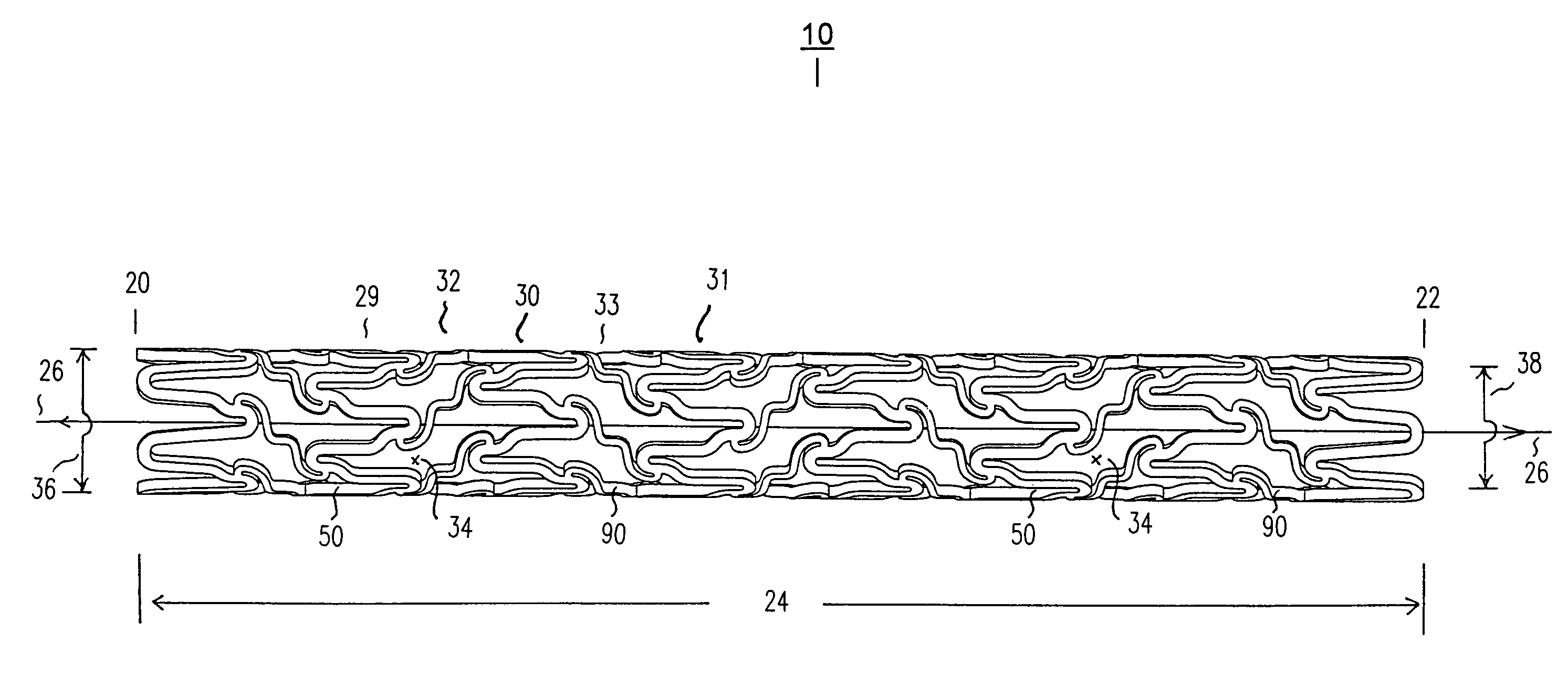
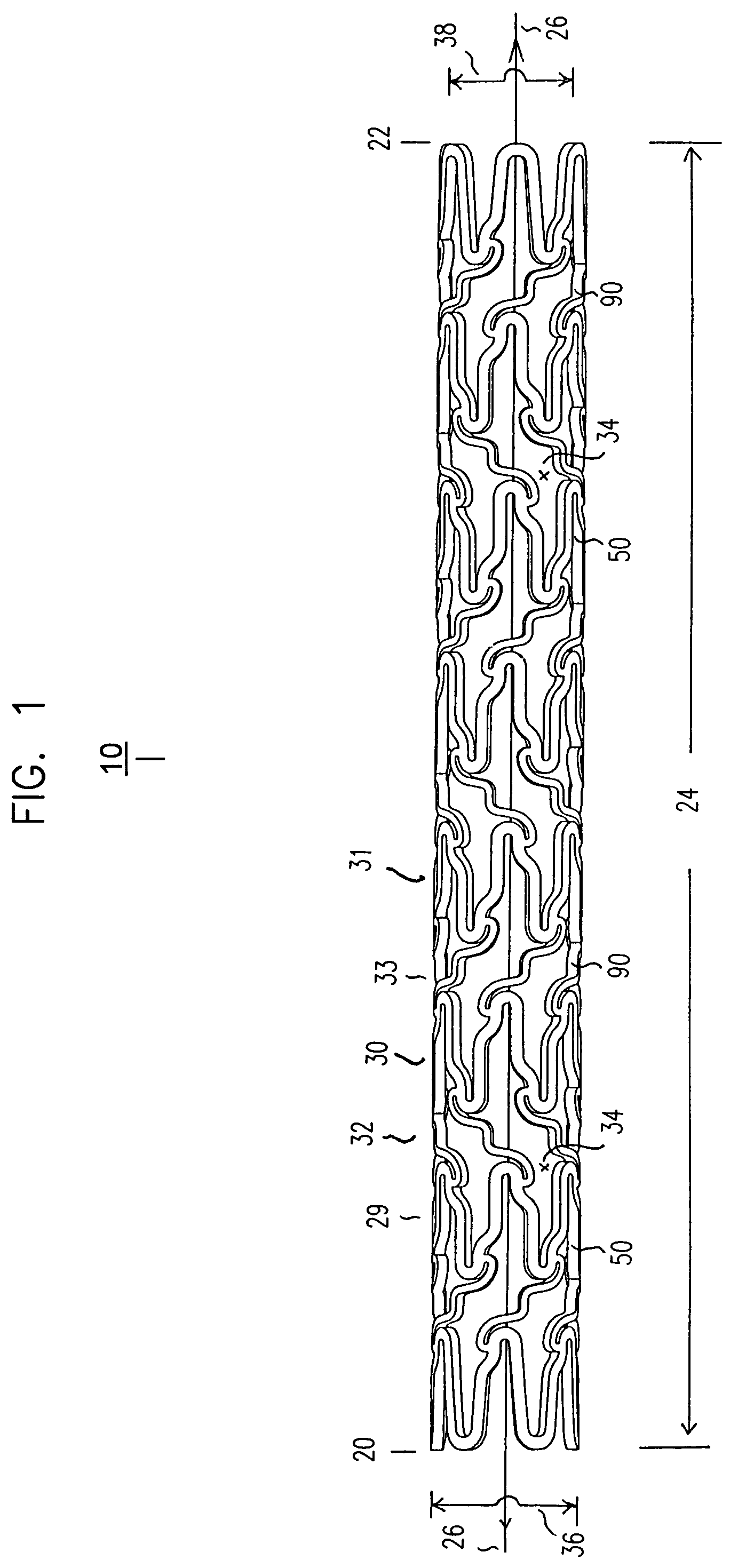
[0022]Various embodiments of a stent include a combination of maximum possible flexibility and conformability in the stent, full vessel coverage with optimal metal fraction, evenly expanding stent struts, excellent radial strength and radiopacity, and smooth surface modulations in both delivery and deployed phases of the stent life cycle. To arrive at these goals, many detailed new innovations are added to the expansion and connecting strut designs of the stent. Expansion strut design is largely responsible for radial strength and radiopacity, while connecting strut design is largely responsible for flexibility and smooth surface modulations. Full vessel coverage and uniform stent expansion are largely from interaction between expansion and connecting struts. Various embodiments of the stent demonstrate a balance among these multiple qualities, using smart expansion struts and flexible connecting struts in a seamlessly integrated stent network.
[0023]Various embodiments of the stent are specifically designed to be both very flexible and fully cover vessel surface inside the vascular lumen. The stent can have both characteristics of vessel coverage and flexibility, particularly for coronary use.
[0024]Various embodiments of the stent are well designed for both the delivery phase and the deployed phase of the stent life cycle. Both flexibility and good vessel coverage are in a right balance in various embodiments of the stent have. Various embodiments of the stent include certain configurations in expansion and connecting struts of the stent.
Problems solved by technology
The flexible current stents generally have poor vessel coverage, tissue prolapse, rough surface modulation and increased restenosis rate.
On the other hand, a good vessel coverage stent in the current state of art has better vessel coverage but not flexible enough for easy delivery and efficient procedure.
Although the brachytherapy (radiation treatment) has proved to be reasonably effective in further reducing restenosis after stent implant, using brachytherpy is very cumbersome, inconvenient and costly.
The laser and atherectomy devices proved to be marginally useful in this purpose with added costs.
Method used
Image
Click on the blue label to locate the original text in one second.
Reading with bidirectional positioning of images and text.
Examples
Embodiment Construction
is hereafter described with specific reference being made to the drawings.
[0043]FIG. 1 shows a side elevation view of an embodiment of a stent, such as a tubular stent.
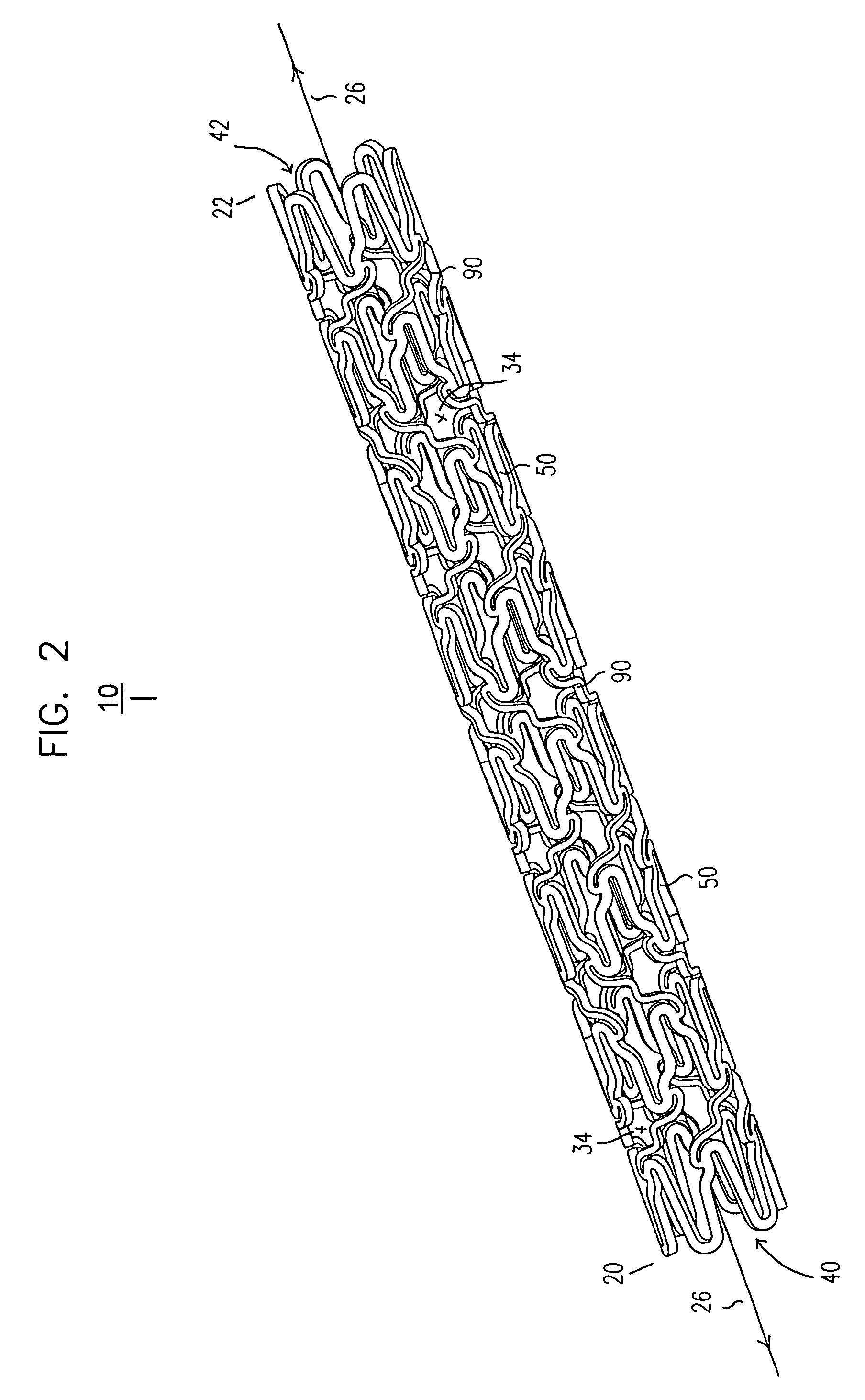
[0044]FIG. 2 shows an isometric view of an embodiment of a stent, such as a tubular stent.
[0045]FIG. 3 shows a cut-open view of an embodiment of a stent. Various expansion columns and connecting strut columns are shown.
[0046]FIG. 4 shows a magnified view of a middle section of an embodiment of a stent, such as a stent of FIGS. 1, 2, and / or 3. Some details are shown of expansion columns.
[0047]FIG. 5 shows a magnified view of a middle section of an embodiment of a stent, such as a stent of FIGS. 1, 2, and / or 3. Some details are shown of connecting strut columns.
[0048]FIG. 6 shows a side elevation view of an embodiment of a stent, such as a tubular stent.
[0049]FIG. 7 shows an isometric view of an embodiment of a stent, such as a tubular stent.
[0050]FIG. 8 shows a cut-open view of an embodiment of a stent. Various expansi...
PUM
Abstract
Various intravascular stents, such as intracoronary stents, include improved expansion and connecting strut designs. Such stents can be both very flexible and fully cover vessel surface inside the vascular lumen, and be well designed for both the delivery phase and the deployed phase of the stent life cycle.
Description
CROSS REFERENCE TO RELATED APPLICATION[0001]This application is a continuation-in-part (CIP) of U.S. application Ser. No. 09 / 960,861, filed Sep. 21, 2001, which claims the benefit of U.S. Provisional Application 60 / 234,614, filed Sep. 22, 2000.[0002]This application is also a continuation-in-part (CIP) of U.S. application Ser. No. 09 / 963,125, filed Sep. 24, 2001, which claims the benefit of U.S. Provisional Application 60 / 235,167, filed Sep. 23, 2000.[0003]This application is also a continuation-in-part (CIP) of U.S. application Ser. No. 09 / 960,868, filed Sep. 21, 2001, which claims the benefit of U.S. Provisional Application 60 / 235,115, filed Sep. 23, 2000.[0004]This application is also a continuation-in-part (CIP) of U.S. application Ser. No. 09 / 962,792, filed Sep. 24, 2001, which claims the benefit of U.S. Provisional Application 60 / 235,180, filed Sep. 25, 2000.[0005]This application is also a continuation-in-part (CIP) of U.S. application Ser. No. 09 / 942,077, filed Aug. 28, 2001...
Claims
Application Information
Patent Timeline
Application Date:The date an application was filed.
Publication Date:The date a patent or application was officially published.
First Publication Date:The earliest publication date of a patent with the same application number.
Issue Date:Publication date of the patent grant document.
PCT Entry Date:The Entry date of PCT National Phase.
Estimated Expiry Date:The statutory expiry date of a patent right according to the Patent Law, and it is the longest term of protection that the patent right can achieve without the termination of the patent right due to other reasons(Term extension factor has been taken into account ).
Invalid Date:Actual expiry date is based on effective date or publication date of legal transaction data of invalid patent.

