Intravascular stent and assembly

a technology of stents and stents, applied in the field of intravascular stents, can solve the problems of poor vessel coverage of flexible current stents, tissue prolapse, rough surface modulation,

Inactive Publication Date: 2004-07-08
BOSTON SCI SCIMED INC
View PDF99 Cites 90 Cited by
  • Summary
  • Abstract
  • Description
  • Claims
  • Application Information

AI Technical Summary

Problems solved by technology

The flexible current stents generally have poor vessel coverage, tissue prolapse, rough surface modulation and increased restenosis rate.
On the other hand, a good vessel coverage stent in the current state of art has better vessel coverage but not flexible enough for easy delivery and efficient procedure.
Although the brachytherapy (radiation treatment) has proved to be reasonably effective in further reducing restenosis after stent implant, using brachytherpy is very cumbersome, inconvenient and costly.
The laser and atherectomy devices proved to be marginally useful in this purpose with added costs.

Method used


Image

  • Intravascular stent and assembly
  • Intravascular stent and assembly
  • Intravascular stent and assembly

Examples


Embodiment Construction

is hereafter described with specific reference being made to the drawings.

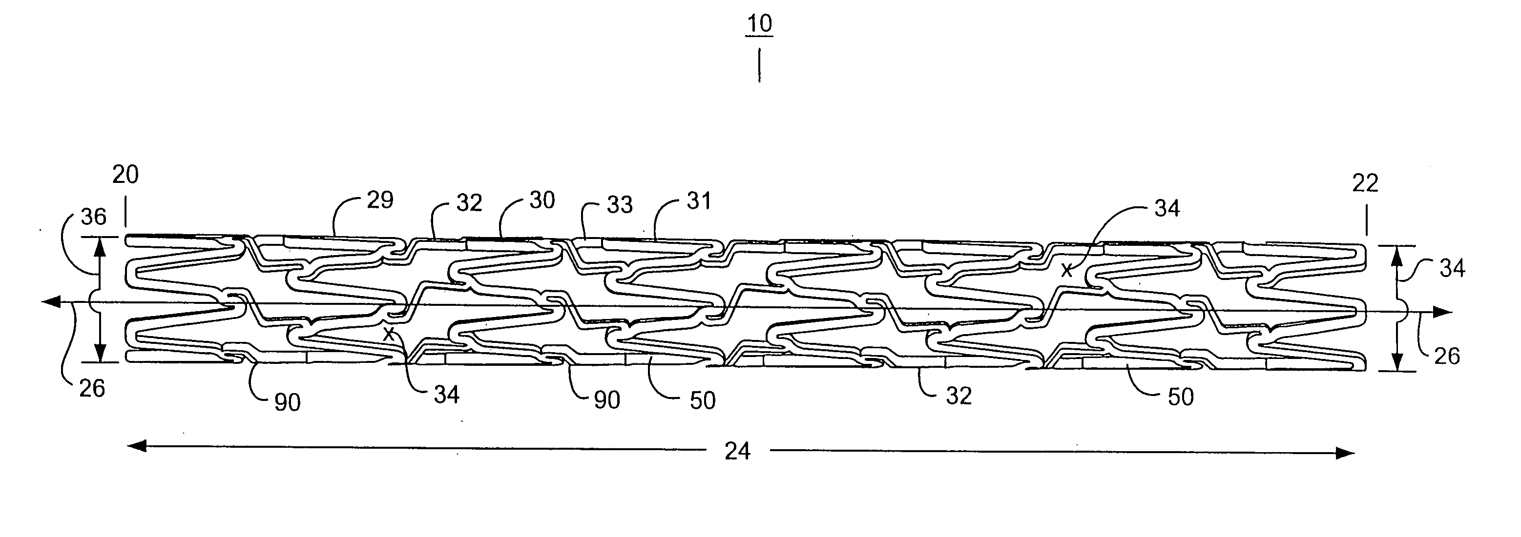
[0043] FIG. 1 shows a side elevation view of an embodiment of a stent, such as a tubular stent.

[0044] FIG. 2 shows an isometric view of an embodiment of a stent, such as a tubular stent.

[0045] FIG. 3 shows a cut-open view of an embodiment of a stent. Various expansion columns and connecting strut columns are shown.

[0046] FIG. 4 shows a magnified view of a middle section of an embodiment of a stent, such as a stent of FIGS. 1, 2, and / or 3. Some details are shown of expansion columns.

[0047] FIG. 5 shows a magnified view of a middle section of an embodiment of a stent, such as a stent of FIGS. 1, 2, and / or 3. Some details are shown of connecting strut columns.

[0048] FIG. 6 shows a side elevation view of an embodiment of a stent, such as a tubular stent.

[0049] FIG. 7 shows an isometric view of an embodiment of a stent, such as a tubular stent.

[0050] FIG. 8 shows a cut-open view of an embodiment of a stent. Various...


PUM


Abstract

Various intravascular stents, such as intracoronary stents, include improved expansion and connecting strut designs. Such stents can be both very flexible and fully cover vessel surface inside the vascular lumen, and be well designed for both the delivery phase and the deployed phase of the stent life cycle.

Description

[0001] This application is a continuation-in-part (CIP) of U.S. application Ser. No. 09 / 960,861, filed Sep. 21, 2001, which claims the benefit of U.S. Provisional Application 60 / 234,614, filed Sep. 22, 2000.[0002] This application is also a continuation-in-part (CIP) of U.S. application Ser. No. 09 / 963,125, filed Sep. 24, 2001, which claims the benefit of U.S. Provisional Application 60 / 235,167, filed Sep. 23, 2000.[0003] This application is also a continuation-in-part (CIP) of U.S. application Ser. No. 09 / 960,868, filed Sep. 21, 2001, which claims the benefit of U.S. Provisional Application 60 / 235,115, filed Sep. 23, 2000.[0004] This application is also a continuation-in-part (CIP) of U.S. application Ser. No. 09 / 962,792, filed Sep. 24, 2001, which claims the benefit of U.S. Provisional Application 60 / 235,180, filed Sep. 25, 2000.[0005] This application is also a continuation-in-part (CIP) of U.S. application Ser. No. 09 / 942,077, filed Aug. 28, 2001, which claims the benefit of U.S...

Claims


Application Information

Patent Timeline
Patent Type & Authority Applications(United States)
IPC IPC(8): A61F2/00A61F2/06A61F2/90
CPCA61F2/91A61F2/915A61F2002/91525A61F2002/91533A61F2230/0054A61F2002/91583A61F2250/0036A61F2250/0067A61F2002/91558
Inventor JANG, G. DAVID
Owner BOSTON SCI SCIMED INC
Why Eureka
Try Eureka