Airflow control mechanism

a control mechanism and airflow technology, applied in the direction of valve operating means/releasing devices, cleaning equipment, service pipe systems, etc., can solve the problems of less precise control for users, more expensive and difficult manufacturing, and less control for users, etc., to achieve reliable operation, high degree of precise control, and low cost.

Inactive Publication Date: 2010-08-24
BLACK & DECKER INC
View PDF14 Cites 16 Cited by
  • Summary
  • Abstract
  • Description
  • Claims
  • Application Information

AI Technical Summary

Problems solved by technology

However, it also has the disadvantage that it gives little control to the user beyond two settings in which the bleed valve is either open or closed.
In order to alleviate this problem somewhat, a more sophisticated version of the bleed valve may also allow the size of the second, clean air inlet to be varied but this gives little precise control to the user.
This second technique has the advantage that the mechanism allows for sophisticated and precise control of the volume of air entering the dirty air inlet by the user, but it also has the disadvantage that it is more expensive and difficult to manufacture than a bleed valve.
Because of its greater degree of complication, it is also more liable to malfunction than a bleed valve.

Method used


Image

  • Airflow control mechanism
  • Airflow control mechanism
  • Airflow control mechanism

Examples


Embodiment Construction

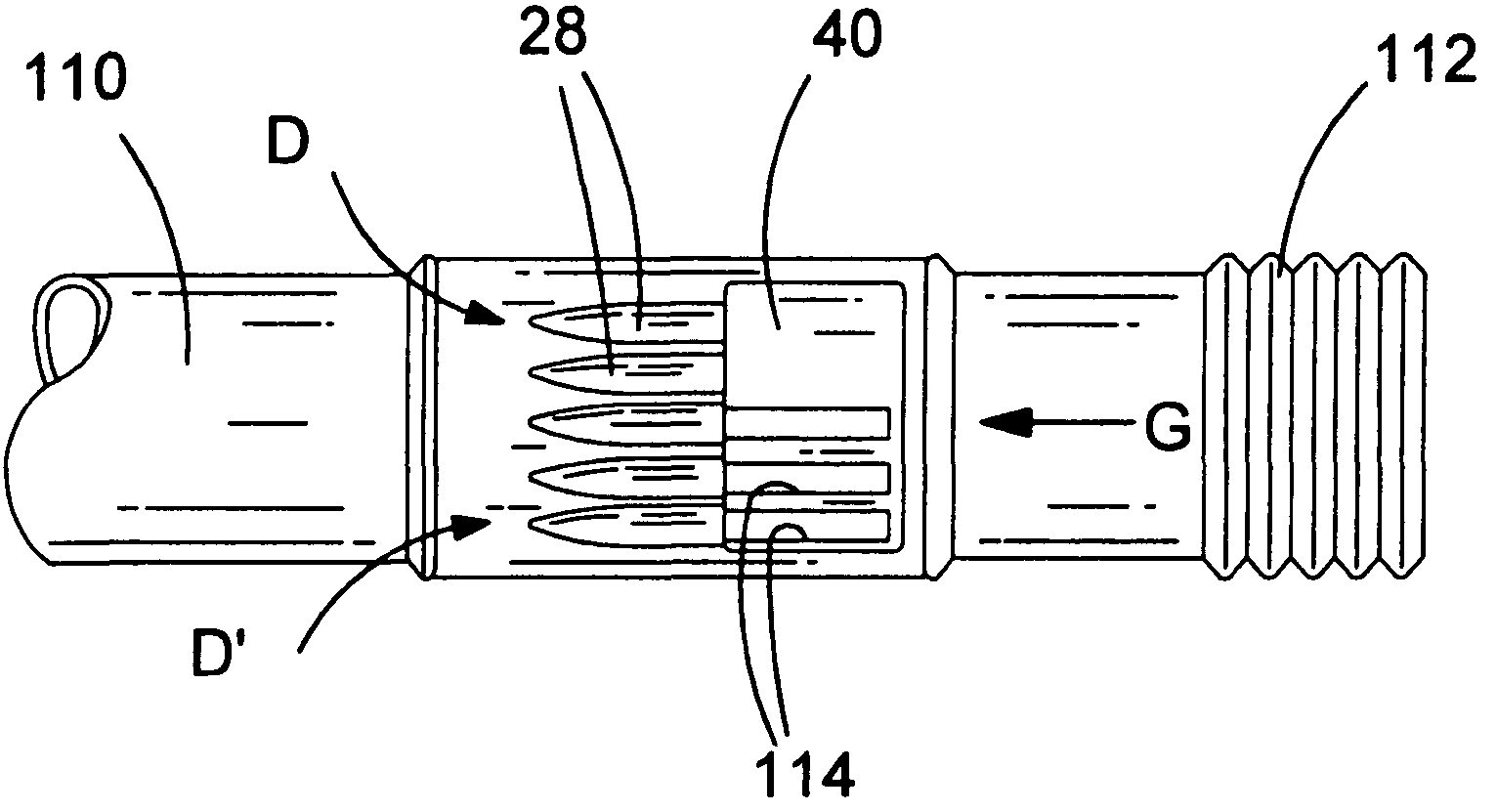
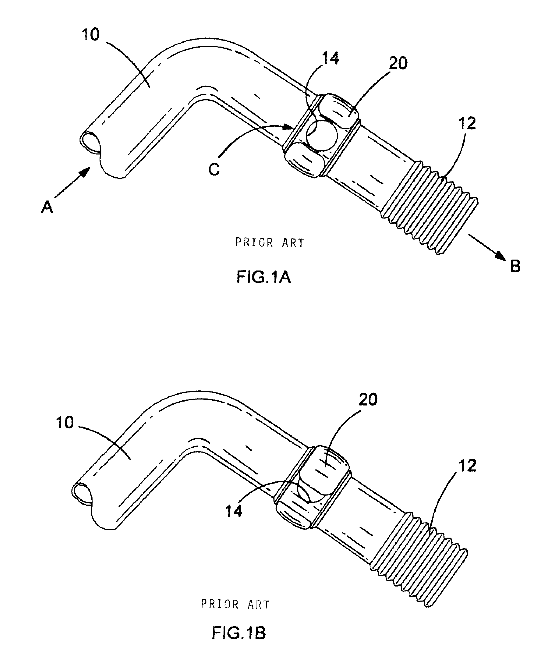
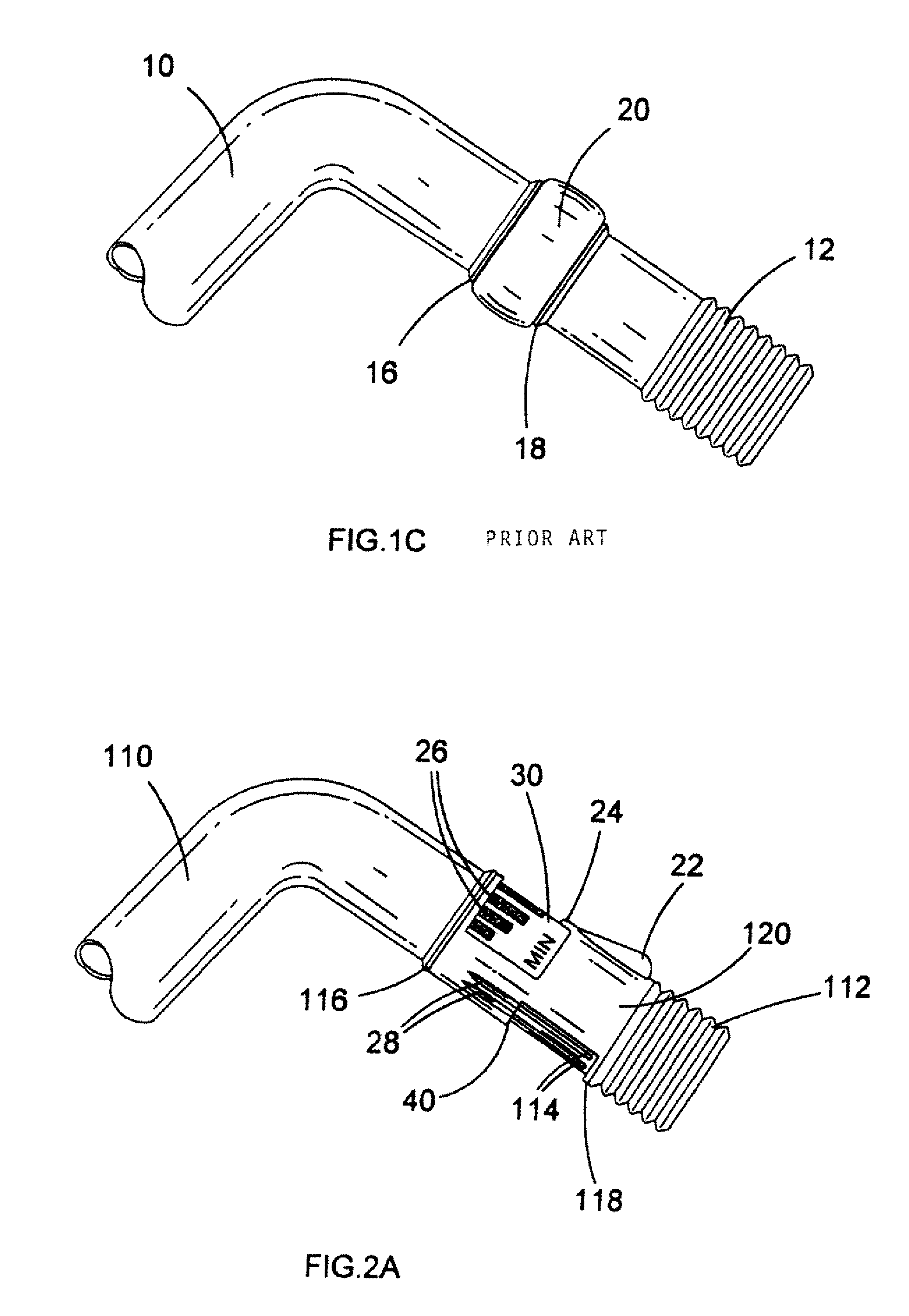
[0020]Referring firstly to FIG. 1A, there is shown part of a vacuum cleaner wand comprising a prior art bleed valve. The wand comprises a rigid tubular portion 10 and a flexible hose portion 12. An end of the rigid tubular portion 10 remote from the flexible hose portion 12 is provided with an inlet for dirty air (not shown), for example as part of a floor-cleaning head. An end of the flexible hose portion 12 remote from the rigid tubular portion 10 is in turn connected to a vacuum cleaner body (also not shown). Thus during operation of the vacuum cleaner, dirty air enters the rigid tubular portion 10 in the direction indicated in FIG. 1A by arrow A and exits the flexible hose portion 12 in the direction indicated in FIG. 1A by arrow B. An opening 14 is also formed in rigid tubular portion 10, which provides a second inlet for clean air. This enters the wand during operation of the vacuum cleaner in the direction indicated in FIG. 1A by arrow C. Rigid tubular portion 10 further comp...


PUM


Abstract

The present invention provides an airflow control mechanism comprising a conduit for air having an inlet located at a first end thereof and an outlet located at a second end thereof; a first opening formed in a side of said conduit and able to provide a secondary inlet thereto; a movable collar at least partially surrounding said conduit at a location alignable with said first opening, such that said collar is able to at least partially occlude said first opening; further comprising a second opening beside the first opening as part of the secondary inlet, wherein the collar is also alignable with the second opening, such that the collar is able to at least partially occlude the second opening at the same time as the first opening. Thus with this airflow control mechanism, a user may select whether to occlude both the first and the second openings, in which case air will pass directly from the inlet to the outlet without any air also entering through the secondary inlet, or to occlude neither the first and second openings, in which case air entering the secondary inlet will contribute to the total amount of air exiting the outlet, or to occlude just one of the first and second openings, in which case, a fixed amount of air which is less than the secondary inlet being fully open, but more than the secondary inlet being fully closed, will enter through the secondary inlet and contribute to the total amount of air exiting the outlet. Thus the user will be provided with a highly predictable and repeatable setting for the airflow control mechanism between the fully open and fully closed positions of the secondary inlet.

Description

FIELD OF THE INVENTION[0001]The present invention concerns a mechanism for controlling the airflow in an airflow pathway. It is particularly applicable to the airflow pathway in a vacuum cleaner, but is equally applicable to the airflow pathway in any air-moving system requiring control.BACKGROUND OF THE INVENTION[0002]In conventional vacuum cleaners, an airflow pathway comprises an inlet for dirty air, which is provided for example as part of a floor-cleaning head, an outlet for clean air and a source of suction power. The source of suction power, which is typically a motor and a fan driven by the motor, generates a pressure differential between the dirty air inlet and the clean air outlet, which draws air in through the inlet and expels the air through the outlet. A filter or other separation device such as a cyclone located in fluid communication between the inlet and the outlet separates out dust and dirt from the air as it passes along the airflow pathway. In conventional vacuu...

Claims


Application Information

Patent Timeline
Patent Type & Authority Patents(United States)
IPC IPC(8): F16K11/06
CPCA47L9/0072Y10T137/87627Y10T137/8275Y10T137/86823
Inventor PEARS, BARRY
Owner BLACK & DECKER INC
Why Eureka
Try Eureka