Slider for linear motion rolling guide unit

a technology of sliding guide unit and linear motion, which is applied in the direction of bearings, shafts and bearings, bearings, etc., can solve the problems of increasing manufacturing costs, and achieve the effects of reducing manufacturing costs, reducing manufacturing costs, and ensuring and lubricating uniformity

Active Publication Date: 2010-08-24
NIPPON THOMPSON
View PDF2 Cites 4 Cited by
  • Summary
  • Abstract
  • Description
  • Claims
  • Application Information

AI Technical Summary

Benefits of technology

[0014]It is an object of the present invention to provide a slider for a linear motion rolling guide unit which is capable of ensuring a smooth rolling movement and a reliable lubricating capability and also of eliminating the need for accurate dimension control to reduce the manufacturing costs.
[0019]In short, according to the present invention, even if a dimensional error or an assembly error occurs in the lubricating member, the end cap and the like, the error can be absorbed by the recessed area, so that an unnecessary difference in level is not produced between the lubricating face and the turning corner, and additionally, the rolling elements can be reliably and sufficiently lubricated.
[0020]Then, such absorption of the dimensional error or the assembly error eliminates the need of precision dimensional control, thus achieving easy assembling work. As a result, the degree of flexibility in design is increased, making it possible to significantly reduce the costs in the manufacturing process.
[0021]In addition, according to the present invention, since the lubricating face is exposed on the arced face of the turning corner, the length of the portion of the lubricating face making contact with the rolling elements can be selectively determined simply by changing the amount of exposure of the lubricating face. Accordingly, an unnecessary increase in the contact length between the rolling elements and the lubricating face is prevented, so that the rolling elements will not be coated with a large amount of lubricant, and there will not exhaust the lubricant promptly.
[0022]Further, because the recessed areas also have the function of accumulating oil, abraded powder and the like, the sliding movement of the slider is made smoother.

Problems solved by technology

For this purpose, a complicated manufacturing process and intricate assembling process are required, resulting in an increase in manufacturing costs.

Method used


Image

  • Slider for linear motion rolling guide unit
  • Slider for linear motion rolling guide unit
  • Slider for linear motion rolling guide unit

Examples


Embodiment Construction

[0041]A slider for a linear motion rolling guide unit according to the present invention will be described below with reference to FIG. 1 to FIG. 17.

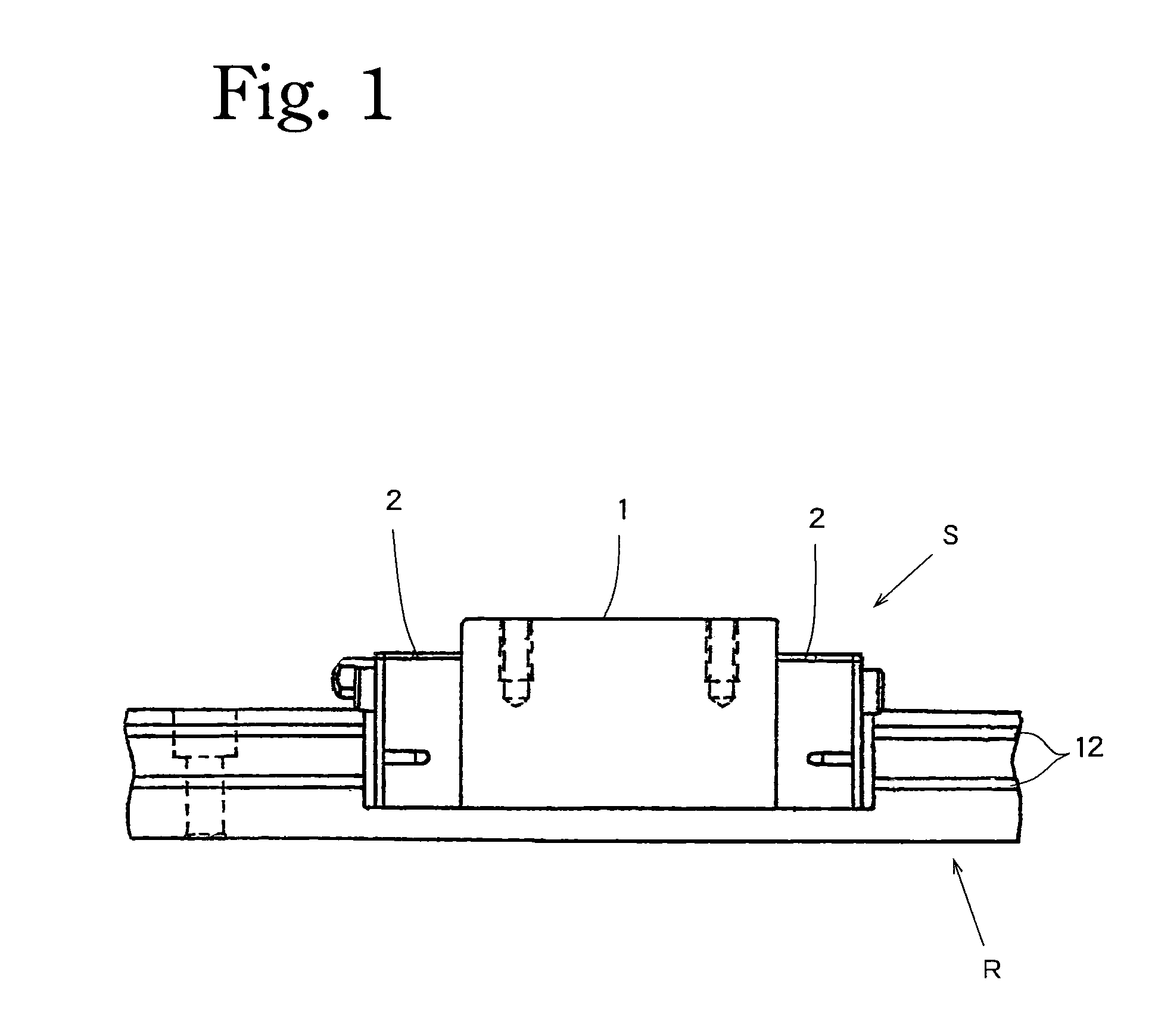
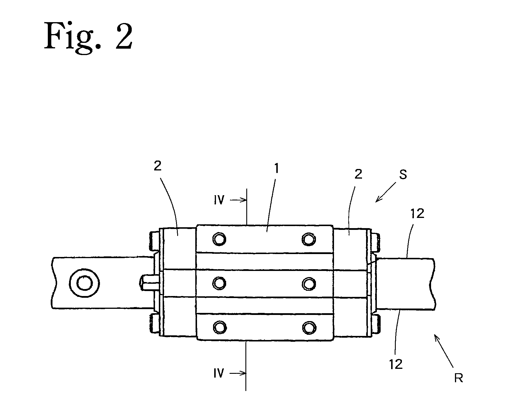
[0042]As illustrated in FIG. 1 to FIG. 3, a slider S of the present invention, which slides in the longitudinal direction of a track rail R, comprises a casing 1 and a pair of end caps 2 respectively attached to the two ends of the casing 1. As shown in FIG. 3, the casing 1 has a pair of arms 1a, and also each of the end caps 2 has a pair of arms 2a. The pair of arms 1a and the pair of arms 2a are located opposite each other on either side of the track rail R as shown in FIG. 3 such that the slider S straddles the track rail R.

[0043]As illustrated in FIG. 4, each of the arms 1a of the casing 1 has a pair of rolling paths 3, 4 formed therein.

[0044]On the other hand, each of the end caps 2 is shown in FIG. 5 to FIG. 7. As shown in FIG. 5, the end cap 2 has a face 5 which is in contact with the casing 1 and fixed to the casing 1. As shown ...


PUM


Abstract

A slider for a linear motion rolling guide unit can ensure a smooth rolling movement and a reliable lubricating capability and eliminate the need for accurate dimension control to reduce the manufacturing costs. A lubricating member A has a lubricating face 20 exposed on an outer peripheral face of a turning corner 10 in an end cap 2. The rolling elements 11 are lubricated by making contact with the lubricating face 20 while rolling through the turning corner. The lubricating face 20, exposed on the arced face 10b of the turning corner, and the outer peripheral face of the turning corner maintain the relation of crossing each other at two intersections. The lubricating face 20 is longer than the distance between the two intersections. Recessed areas 21 are formed between the outer peripheral face of the turning corner 10 and the lubricating face 20 in the surplus length regions.

Description

BACKGROUND OF THE INVENTION[0001]1. Field of the Invention[0002]This invention relates to a slider used in a linear motion rolling guide unit and causing rolling elements to roll on raceway faces provided on a track rail to achieve a smooth relative movement on the rail.[0003]2. Description of the Related Art[0004]Conventionally, this type of slider for a linear motion rolling guide unit is known from JP-2007-100951A.[0005]The slider comprises a casing and end caps secured at the two ends of the casing, and provides for circulation paths which are made up of rolling paths formed in the casing and turning corners formed in the end caps for allowing the rolling elements to move around the circulation paths. The end caps have mounted on them lubricating members impregnated with a lubricant. A portion of each of the lubricating members is exposed to the inside of each of the turning corners formed in the end caps. FIG. 18 shows a specific structure of the lubricating member and the turn...

Claims


Application Information

Patent Timeline
Patent Type & Authority Patents(United States)
IPC IPC(8): F16C33/10F16C29/06
CPCF16C29/065F16C33/6611F16C33/6648F16C33/6659F16C2300/02
Inventor KUWABARA, HIDEKIKAKEI, SHIGEKI
Owner NIPPON THOMPSON
Why Eureka
Try Eureka