In place rotation of images for low memory systems

a low-memory system and image rotation technology, applied in the field of computer image manipulation, can solve the problems of poor use of memory bandwidth, inability to access external memory, and the cost of external memory accessing is most likely to be based on the latency of the access and not the actual data movement itsel

Active Publication Date: 2010-08-24
TEXAS INSTR INC
View PDF9 Cites 36 Cited by
  • Summary
  • Abstract
  • Description
  • Claims
  • Application Information

AI Technical Summary

Problems solved by technology

In fact, this is not the case.
This makes poor use of memory bandwidth.
Most of the cost of accessing external memory lies in the latency of the access and not the actual data movement itself.
Depending on the locality of a given garland, a data cache may reduce redundant memory accessed, however this seems unlikely.
Care would be required in assembling the endpoints of garland segments, but this isn't insurmountable.
The tile problem would be similar even if one data word stored only one pixel.
The problem with using tiles is that image is generally stored in memory with all pixels from the current row stored after all pixels from the preceding row.
Additional problems occur when the image is non-square.
The problem is one dimensional since memory is one dimensional.
The row pitch of the pixel information within each tile retains the row pitch of the original image, which is undesirable.
One minor issue may arise if the image is a tall image with the number of rows (H) greater than the number of columns (W).

Method used


Image

  • In place rotation of images for low memory systems
  • In place rotation of images for low memory systems
  • In place rotation of images for low memory systems

Examples


Embodiment Construction

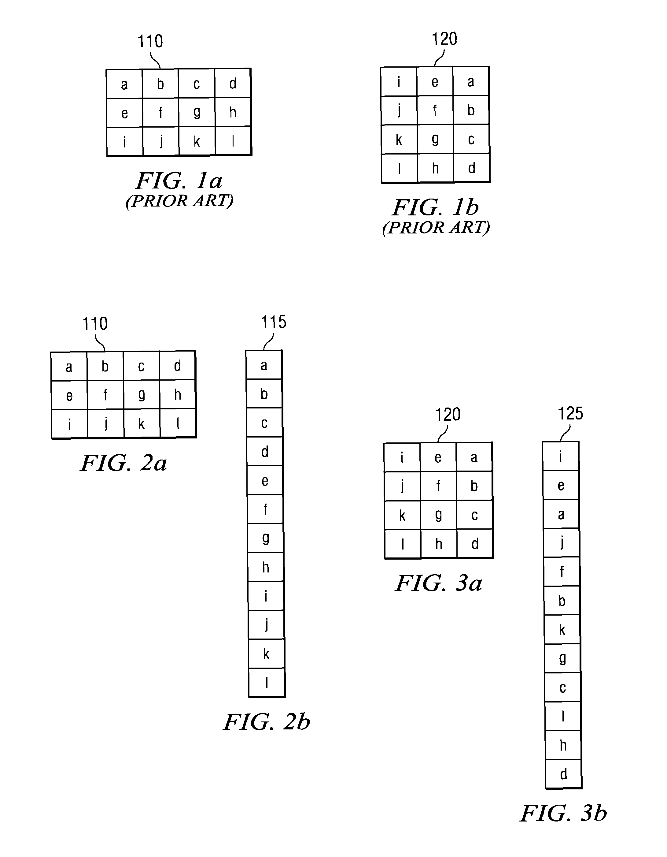
[0019]FIG. 1 illustrates an example rotation operation to which this invention applies. FIG. 1a illustrates original image 110. Original image 110 is a three row by four column image including pixels a to l. FIG. 1b illustrates rotated image 120. Rotated image 120 is a four row by three column image of the same pixels a to l.

[0020]Image rotation according to the prior art requires two image buffers as large as the original image. The first image buffer stores the original image. The second image buffer stores the rotated image. According to the prior art, image rotation takes place by copying each pixel from its position in the original image into the corresponding position of that pixel in the rotated image. This prior art process requires computation of the position within the rotated image that stores each pixel of the original image. This process is not difficult. The principle disadvantage of this prior art process is the requirement for two image buffers. In systems with littl...


PUM


Abstract

Rotation in the storage domain is a one-one function with the domain equal to the range. This permits an image to be rotated in place. Each image size implies at least one garland of closed chains of pixels. Each image includes a spanning set of these garlands. Rotation in place moves each pixel to the next location on its garland. On completion of a garland by return to the initial pixel, pixels on the next garland are moved. Image rotation is complete after all the garlands have been traversed.

Description

CLAIM OF PRIORITY[0001]This application claims priority under 35 U.S.C. 119(e)(1) to U.S. Provisional Application No. 60 / 659,703 filed Mar. 8, 2005.TECHNICAL FIELD OF THE INVENTION[0002]The technical field of this invention is computer image manipulation.BACKGROUND OF THE INVENTION[0003]Image rotation typically requires two image buffers in memory. One image buffer stores the original image and another stores the rotated image. This takes up a lot of memory. The problem is to reduce memory requirement under the condition that the original image is not required after the rotation.BRIEF DESCRIPTION OF THE DRAWINGS[0004]These and other aspects of this invention are illustrated in the drawings, in which:[0005]FIG. 1 illustrates an original image and a resultant image of an example image rotation;[0006]FIG. 2 illustrates the example original image and a linear memory view of this original image;[0007]FIG. 3 illustrates the example rotated image and a linear memory view of this rotated im...

Claims


Application Information

Patent Timeline
Patent Type & Authority Patents(United States)
IPC IPC(8): G09G5/00
CPCG06T3/606
Inventor KOTHANDARAMAN, SREENIVAS
Owner TEXAS INSTR INC
Why Eureka
Try Eureka