Image orientation for endoscopic video displays

a video display and image orientation technology, applied in the field of video displays, can solve the problems of not receiving a sufficient force for the mechanical pendulum to seek the vertical, requiring enlargement of the instrument, and not being able to manually rotate the camera

Inactive Publication Date: 2005-01-27
KARL STORZ IMAGING INC
View PDF22 Cites 32 Cited by
  • Summary
  • Abstract
  • Description
  • Claims
  • Application Information

AI Technical Summary

Benefits of technology

[0017] In another aspect of the present invention, the view presented by the video display can store a preset angle to accommodate what the surgeon needs to see along the axis of the instruments while conducting his procedure within the body cavity. The compensating rotational signal is modified to provide an image orientation that is preferred by the surgeon. This user supplied value is employed by the microprocessor as an offset to the display image rotation provided by the inertial sensors. This allows the surgeon to have the displayed image rotated to any desired orientation and have the invention maintain the image in that orientation.

Problems solved by technology

That is the very problem.
However, the surgeon is standing up, and the rotating image is distracting to him.
This is impossible when the camera is fixed to the telescope and rotates with it, while the surgeon does not.
However, a pendulum to be useful must have a substantial mass and a substantial arc to work through, requiring enlargement of the instrument.
Even worse, when the slope is very steep, a mechanical pendulum may not receive a sufficient force to seek the vertical.
Sometimes, however, there may be reasons to attach the endoscope such that it cannot rotate with respect to the camera.
In these circumstances it is not possible to manually rotate the camera with respect to the endoscope, so some other means is necessary to right the displayed image.
In addition to the rotation effects, a further perspective distortion occurs from the difference between viewing the objects directly in three-dimensions with the eyes and on a two-dimensional camera image.
This results in objects closest to the endoscope end appearing disproportionately large and also results in horizontal lines appearing tilted in the display.

Method used


Image

  • Image orientation for endoscopic video displays
  • Image orientation for endoscopic video displays
  • Image orientation for endoscopic video displays

Examples


first embodiment

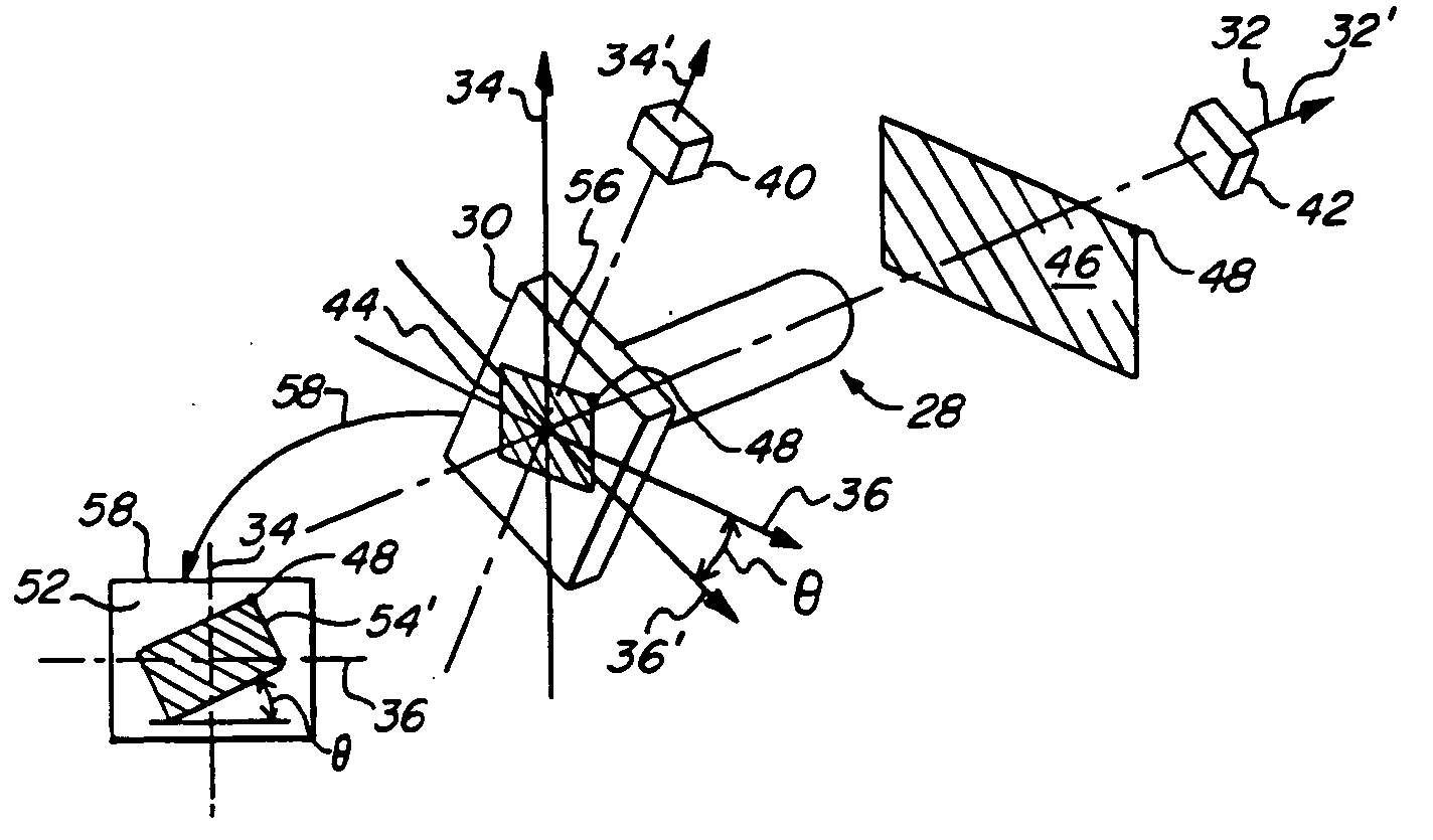
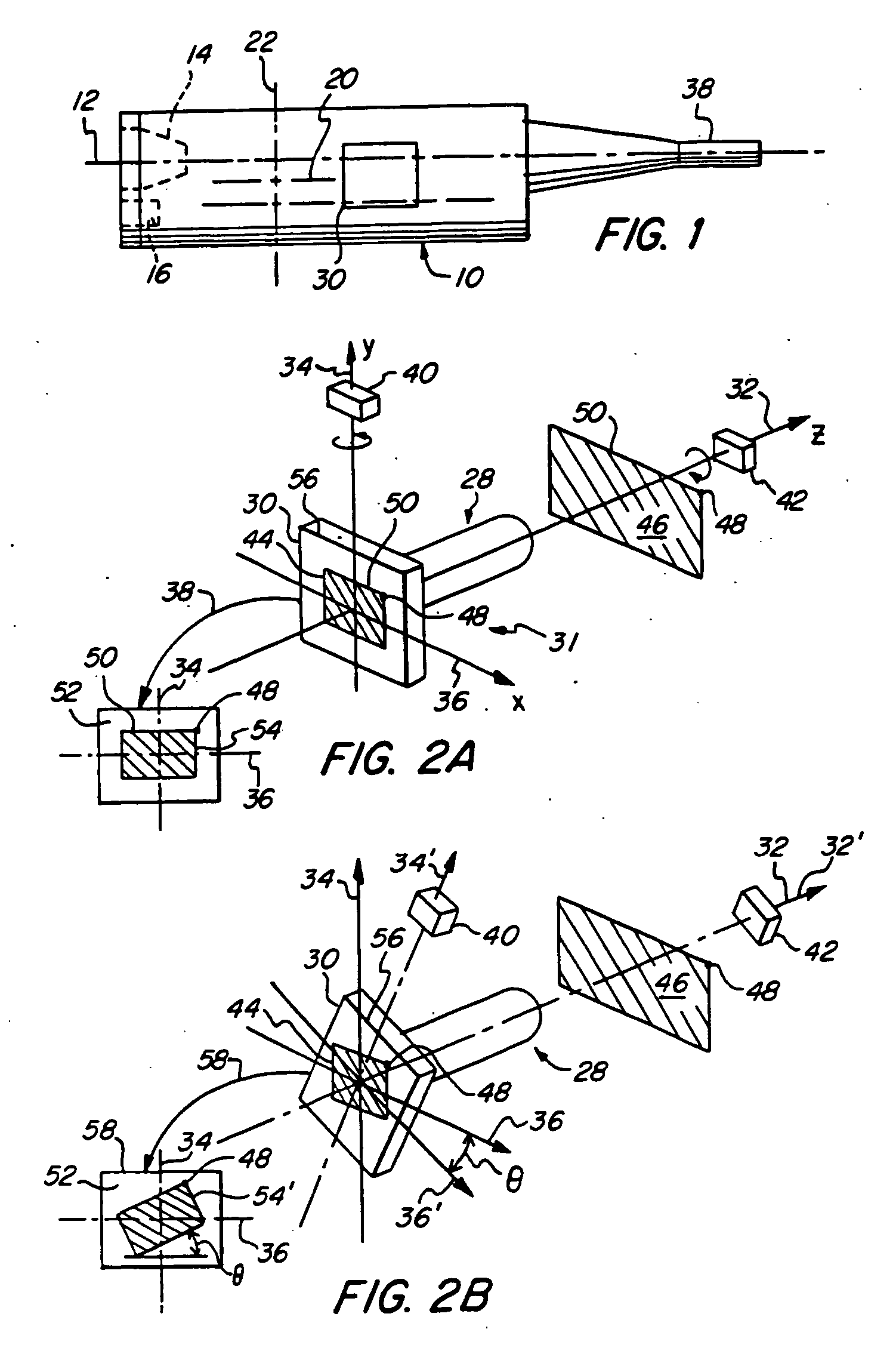
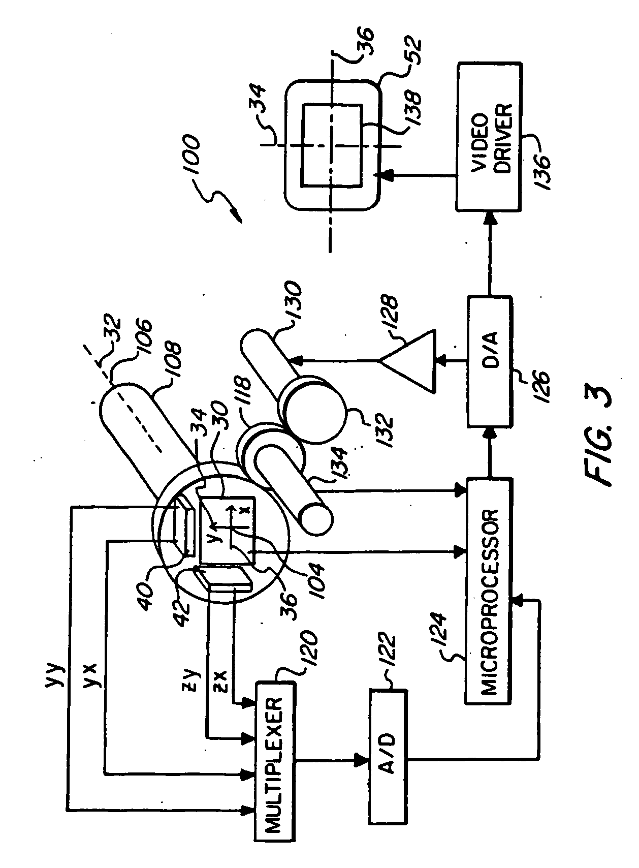
[0052] In a first embodiment shown in FIG. 3, two accelerometers 40, 42 are used to determine angular rotation of image sensor 30 about its optical z-axis 32. When in use, the endoscope will have freedom to tilt in all directions so that the accelerometer will often be responding to a component of vertical gravitational force that is considerably less than its maximum value. In some instances the camera enters the anatomy at an angle that is so extreme that it becomes difficult to determine, by use of a single gravity sensor, in which direction or how much of an automatic angular compensation is required. For example, when z-axis 32 is depressed 60 degrees, the vertical component of gravity to which first accelerometer 42 refers while keeping the image upright is much less than maximum gravity force. The second accelerometer 40 is oriented so that the vertical component of gravity upon it increases as z-axis 32 is depressed. Thus the angular offset required can be derived from the t...

embodiment 300

[0066] Referring to FIG. 5, an alternative embodiment 300 is illustrated wherein the optical image is rotated before reaching the image sensor 304. In this embodiment, the optical image is rotated rather than the image sensor, to accommodate angular rotation of the endoscope about its optical axis. In an illustrative example of this invention, a prism 302 is interposed between the return of the image from the endoscope's distal end 338 and an image sensor 304 at the proximal end. Prism 302 is of a design that rotation of the prism causes a rotation of an output image for a fixed input image and is described in further detail herein below.

[0067] A lens 306 for focusing of the optical image on image sensor 304 may be interposed between prism 302 and image sensor 304. Prism 302 is fixedly disposed on a rotating member 308 whereby a rotation of rotating member 308 rotates prism 302 an equivalent angular amount. For simplicity, prism 302, object lens 306, and image sensor 304 are all sho...


PUM


Abstract

An apparatus and technique for compensating the display of an image obtained from a video camera system associated with an endoscope as it is moved through various orientations are described. The received optical image is converted to an electrical signal with an image sensor that can be a CCD or a CMOS detector. The endoscope video camera system has an inertial sensor to sense rotations of the received image about the optical axis of the endoscope and the sensor's output signals are used to rotate either the image or the image sensor. In case of rotation of the image sensor the rotation sensor can be a gyroscope or a pair of accelerometers. In case of a rotation of the image obtained with the image sensor the inertial sensor, which can be an accelerometer or a gyroscope, the image is rotated within a microprocessor for subsequent viewing on a video display.

Description

CROSS-REFERENCE TO PRIOR APPLICATIONS [0001] This is a divisional of currently pending U.S. patent application Ser. No. 10 / 093,650, filed Mar. 8, 2002, which is a continuation in part of U.S. patent application Ser. No. 09 / 666,692 filed Sep. 21, 2000, now U.S. Pat. No. 6,471,637, which claims the benefit of, under 35 U.S.C. 119(e), provisional patent application Ser. No. 60 / 155,850 of Chatenever filed Sep. 24, 1999.FIELD OF THE INVENTION [0002] This invention relates generally to video displays of images obtained from an endoscope. Specifically this invention relates to a re-orientation of an image as viewed on a display screen to present the image in a preferred relationship to the viewer's reference frame. More specifically this invention relates to inertial sensor techniques for re-orienting such image as it is obtained with an endoscope used to view a body part through an opening in a body. BACKGROUND OF THE INVENTION [0003] An endoscope is an elongated tubular structure that is...

Claims


Application Information

Patent Timeline
Patent Type & Authority Applications(United States)
IPC IPC(8): A61B1/04
CPCA61B1/042A61B1/00045
Inventor CHATENEVER, DAVIDMATTSSON-BOZE, DANIELAMLING, MARC R.
Owner KARL STORZ IMAGING INC
Why Eureka
Try Eureka