Metrology/inspection positioning system

a technology of metal/inspection and positioning system, which is applied in the direction of measuring devices, instruments, scientific instruments, etc., can solve the problems of insufficient space, processing delay, contamination or damage of the wafer by moving the wafer, etc., to avoid inaccuracy, facilitate the identification of features on the wafer, and facilitate the inspection of the wafer.

Inactive Publication Date: 2007-11-13
NANOMETRICS
View PDF49 Cites 34 Cited by
  • Summary
  • Abstract
  • Description
  • Claims
  • Application Information

AI Technical Summary

Benefits of technology

[0012]In accordance with an aspect of the invention, a metrology / inspection system moves the optics and / or measuring equipment above a wafer or sample being inspected or measured. Thus, the metrology or inspection system permits inspection or measurement of a wafer through a window in a processing apparatus. Positioning typically requires pre-alignment to at least roughly determine the location and orientation of the wafer relative to the apparatus, and alignment which precisely identifies the position and orientation of specific features on the wafer. In accordance with an aspect of the invention, the pre-alignment uses edge detection that avoids the inaccuracy arising from pattern recognition systems. With the orientation of the wafer identified, an image rotation system presents an image of the wafer with a standard orientation. The standard orientation facilitates identification of features on the wafer, inspection of the wafer, and operation of metrology equipment to move from point to point on the wafer. More specifically, the image rotation system can maintain the standard orientation of an image of the wafer as an operator moves the optics from one inspection area to the next.
[0013]In one specific embodiment of the invention, the apparatus includes an R-θ stage that positions optics relative to the wafer. A rotation axis of the R-θ stage can either be over or outside a view area of the system. The R-θ stage provides a compact means for positioning the optics while the image rotation and control system permit a user to control motion and view the wafer using perpendicular Cartesian axes and uniform velocity linear motion.

Problems solved by technology

Standalone metrology stations have drawbacks including: the space required for the station; the processing delay for removing, measuring, and returning the wafer for further processing; and possible contamination or damage to the wafer that moving the wafer introduces.
However, the typical processing apparatus lacks a stage or other means capable of precisely positioning a wafer for inspection or moving in the wafer in response to the needs of the metrology equipment.
Further, the space available in and around processing apparatuses is limited so that compact equipment is required.
A disadvantage of a polar stage is the portion of sample 100 in field of view 130 generally appears to rotate when the stage rotates sample 100 to move from one inspection location to another.
With a polar stage, image rotation and variable image motion can easily confuse or disorient the operator when the operator is continuously viewing or inspecting sample 110 and moving the sample from one position to another.

Method used


Image

  • Metrology/inspection positioning system
  • Metrology/inspection positioning system
  • Metrology/inspection positioning system

Examples


Embodiment Construction

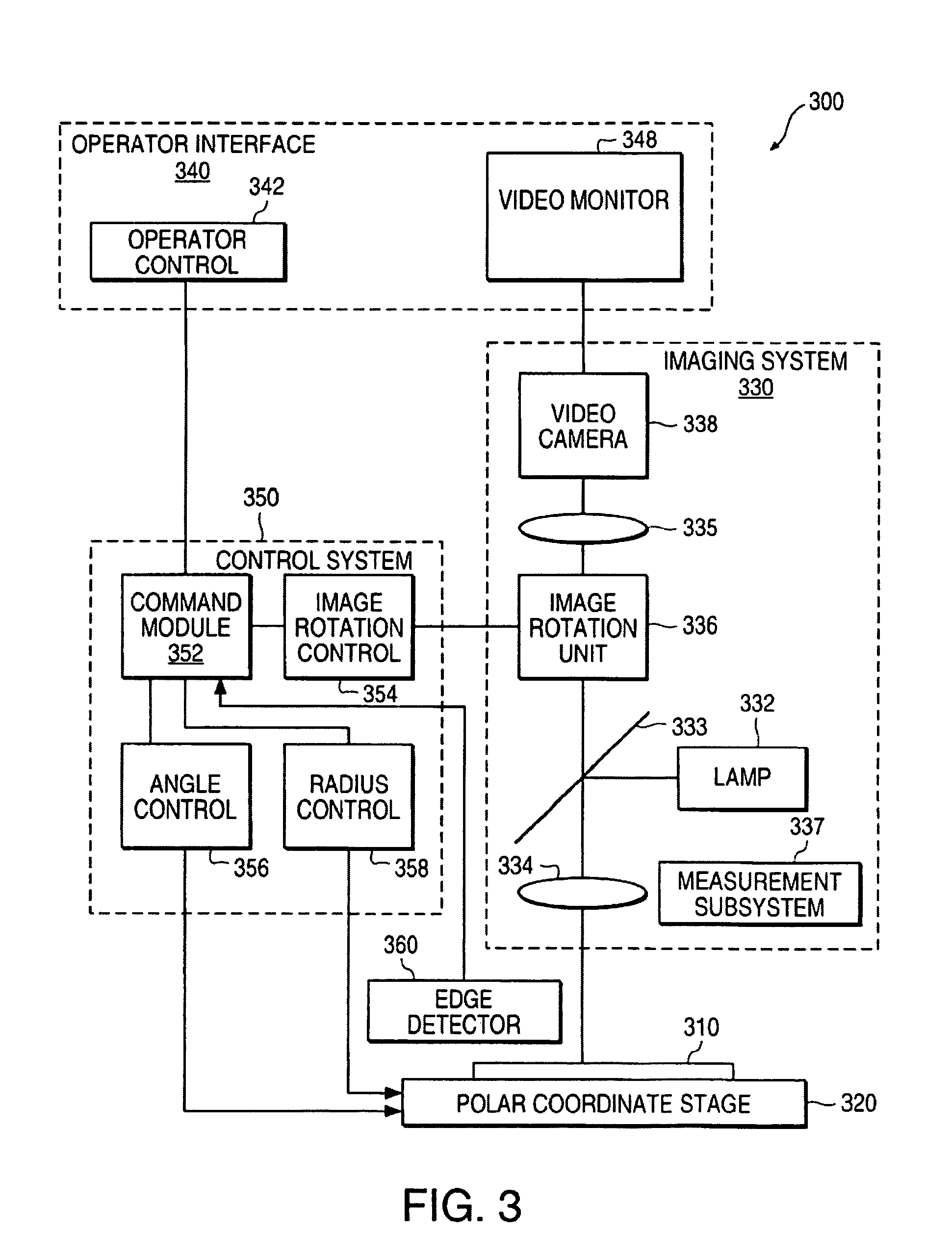
[0025]In accordance with an aspect of the invention, a system for measuring, viewing, or inspecting a sample uses a polar stage on which the sample is mounted. A control system which receives operator commands for linear movement of the sample, generates signals to the polar coordinate stage as reciuired to achieve the linear movement, and rotates the image during motion to preserve a fixed orientation of the sample as viewed by the operator. Accordingly, an operator can easily and intuitively control the direction and velocity of the sample's motion.

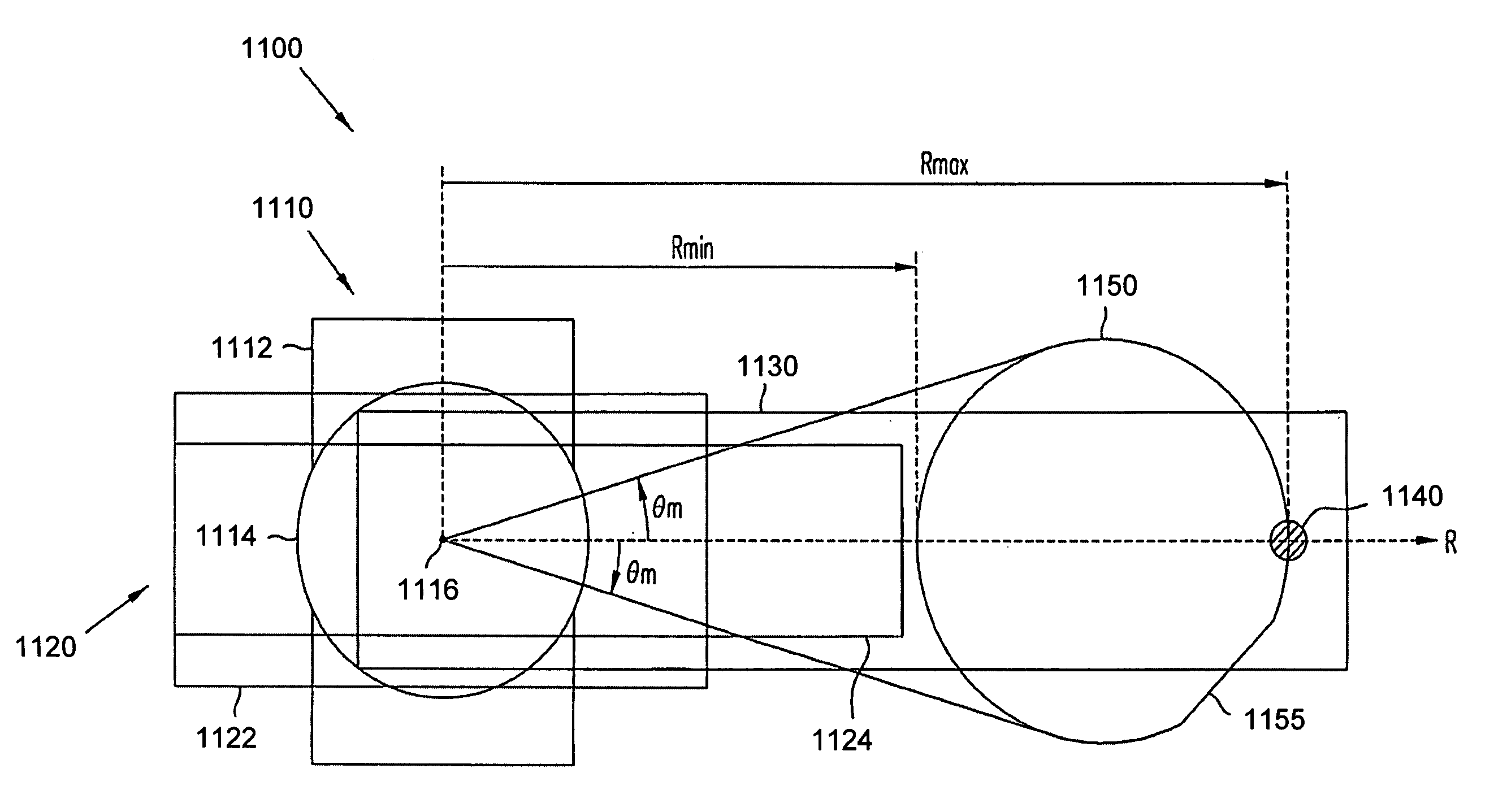
[0026]In accordance with another aspect of the invention, an edge detector detects the location of the edge of a circular sample such as a semiconductor wafer while the polar stage rotates the sample. Processing of the edge measurements allows a precise determination of the position of center of the wafer and identification of an orientation indicator such as a flat or a notch on the edge of the wafer. Accordingly, the stage does not re...


PUM

PropertyMeasurementUnit
rotation axisaaaaaaaaaa
diameteraaaaaaaaaa
diameteraaaaaaaaaa

Abstract

A metrology/inspection system moves the imaging and/or measuring equipment of the system relative to a wafer. Accordingly, measurement or inspection of the wafer does not require that the wafer be mounted on a precision stage. This allows the wafer to be at rest on any structure native in a processing apparatus when the system measures or inspects the wafer. Accordingly, measurement does not require removing the wafer from the processing apparatus and does not delay processing since the wafer can be measured, for example, during a required cool down period of device fabrication process. Alignment of an optical system includes pre-alignment base on edge detection using the optical system and more precise alignment using image recognition. An R-θ stage can position the optical system at inspection areas on the wafer. Image rotation can provide a fixed orientation for all images at the various inspection areas and can maintain the fixed orientation when moving from one inspection area to the next.

Description

CROSS REFERENCE TO RELATED APPLICATION[0001]This is a continuation-in-part of and incorporates by reference in its entirety, co-owned U.S. patent application Ser. No. 09 / 113,484, entitled “System using a Polar Coordinate Stage and Continuous Image Rotation to Compensate for Stage Rotation,” filed Jul. 10, 1998, issued on Nov. 20, 2001 as U.S. Pat. No. 6,320,609 B1.BACKGROUND[0002]Field of the Invention[0003]This invention relates to measurement and inspection systems and particularly to systems and methods for measuring or inspecting specific locations on a wafer while the wafer remains in a processing apparatus.[0004]Description of Related Art[0005]During fabrication of semiconductor devices, wafers containing devices are often inspected or measured to determine whether processes are proceeding as expected. Such measurements provide information that guides adjustments of process parameters to improve the yield of operable devices.[0006]Typically, the inspection or measurement of a ...

Claims


Application Information

Patent Timeline
Patent Type & Authority Patents(United States)
IPC IPC(8): G01B11/00G01B11/14G01N21/00G06K9/00
CPCG01N21/9501
Inventor SPADY, BLAINE R.HEATON, JOHN D.BUCHANAN, ROBERTYARUSSI, RICHARD A.
Owner NANOMETRICS
Why Eureka
Try Eureka