Cargo scanning system

a scanning system and cargo technology, applied in the direction of material analysis, material analysis using wave/particle radiation, instruments, etc., can solve the problems of inability to easily modify, space is generally in substantial demand and short supply, and the scenario is not typically feasible, etc., to achieve cost-effective and accurate deployment, rapid and accurate on uneven surfaces

Inactive Publication Date: 2010-08-24
RAPISCAN SYST INC (US)
View PDF108 Cites 94 Cited by
  • Summary
  • Abstract
  • Description
  • Claims
  • Application Information

AI Technical Summary

Benefits of technology

[0023]The inspection methods and systems of the present invention are portable, mobile, rapidly deployable, and capable of scanning a wide variety of receptacles cost-effectively and accurately on uneven surfaces. In a first embodiment, a self-contained inspection system comprises an inspection module that, in a preferred embodiment, is in the form of a mobile trailer capable of being towed and transported to its intended operating site with the help of a tug-vehicle.
[0024]In one embodiment, the portable inspection system for generating an image representation of target objects using a radiation source, comprises a housing connected to a vehicle, a detector array having a first configuration and a second configuration wherein said array is connected to the housing, and at least one source of radiation wherein said radiation source is capable of being transported to a site by said vehicle and of being positioned separate from the housing, wherein said radiation source is housed in a radiation source box and movable within the radiation source box using an actuator wherein the actuator is operably connected to the radiation source and wherein the actuator provides a translational energy that moves the radiation source between an operational position and a stowed position.

Problems solved by technology

However, these scenarios are not typically feasible.
Space is generally in substantial demand and short supply.
Existing ports operate under a routine that is not easily modified without causing disruption to the entire infrastructure of the port.
With limited space and a need to expand, finding suitable space to accommodate additional inspection facilities along the normal process route remains difficult.
Additionally, selected locations are not necessarily permanent enough for port operators to commit to.
In either case the building footprint is significant depending upon the size of cargo containers to be inspected.
This limits the flexibility of dismantling the entire system for optimum portability and adjustable deployment to accommodate a wide array of different sized cargo, shipments, vehicles, and other containers.
As a result these systems can be complicated to deploy and pose several disadvantages and constraints.
For example, in a moving-scan-engine system the movement of the source and detector, relative to a stationary object, may cause lateral twist and lift and fall of the detector or source, due to movement of the scanner over uneven ground, inducing distortions in the scanned images and faster wear and tear of the scanner system.
Such systems that require a detector-mounted boom to unfold during deployment may cause an unstable shift of the center of gravity of the system off the base, causing the system to tip over.
Further, in the case of moving-scan-engine systems using a “swing arm” boom approach, the driver driving the scanner truck is unable to gauge the possibility of hitting the detector box, mounted on a boom, with a vehicle under inspection (VUI), as the detector box is on the other side of the VUI during scanning and not visible to the driver.
Additionally, with moving-scan-engine systems, the truck supporting the scanner system is always required to move the full weight of the scanner regardless of the size and load of the VUI, putting greater strain on the scanning system.
Further, because of the integrated nature of prior art systems, swapping detector and radiation systems between scanning systems is not feasible.
Also disadvantageous in conventional systems is that they suffer from a lack of rigidity, are difficult to implement, and / or have smaller fields of vision.

Method used


Image

  • Cargo scanning system
  • Cargo scanning system
  • Cargo scanning system

Examples


first embodiment

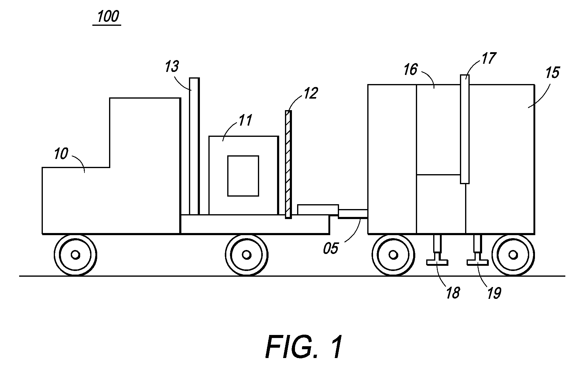
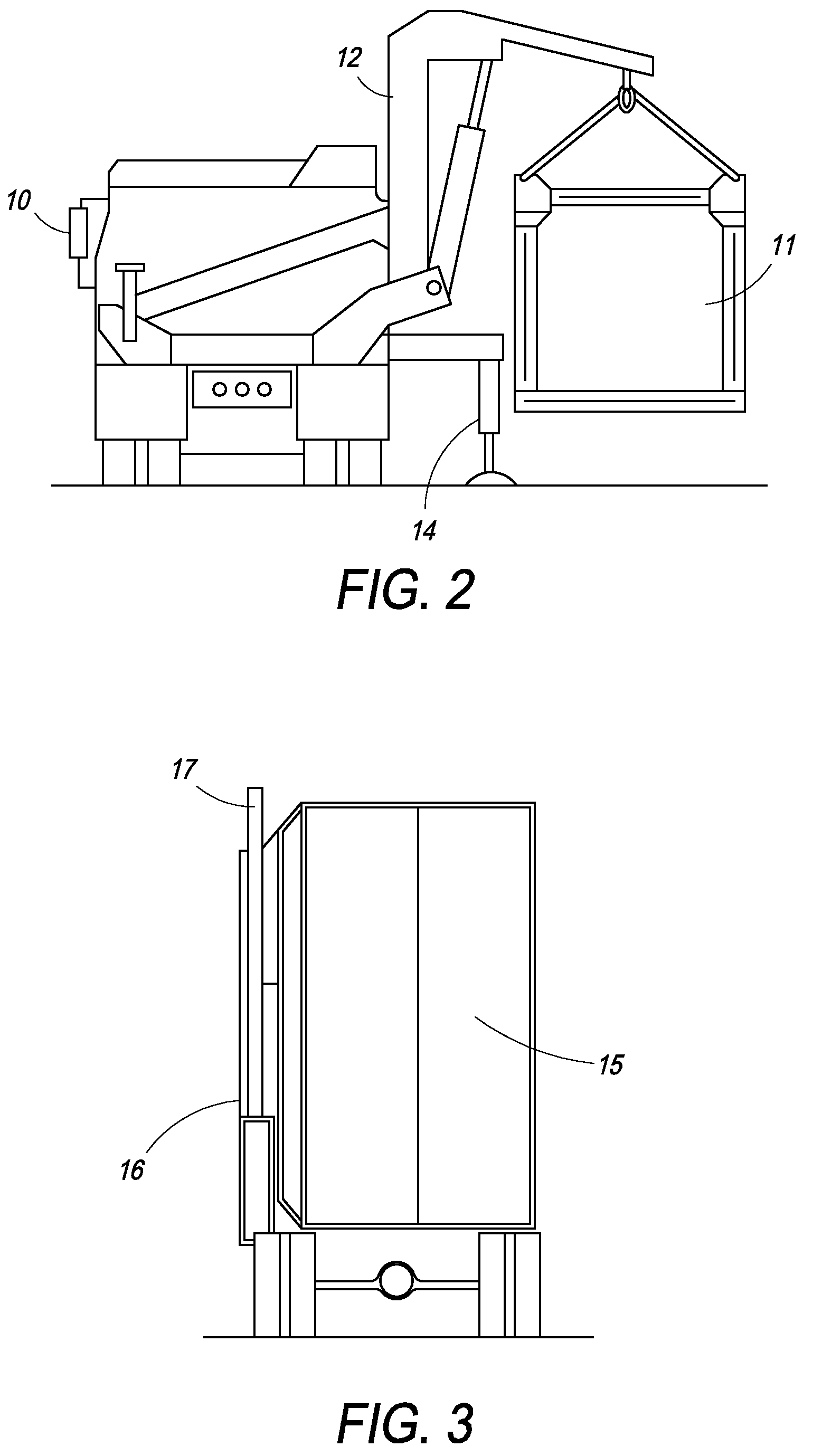
[0081]In a first embodiment, FIG. 1 shows a perspective view of an exemplary self-contained inspection system 100. The system 100 comprises of an inspection module 15 that, in a preferred embodiment, is in the form of a mobile trailer capable of being towed and transported to its intended operating site with the help of a tug-vehicle 10. While the present invention is depicted as a tug vehicle 10 connected to a trailer 15, one of ordinary skill in the art would appreciate that the vehicular portion of the system and inspection module portion of the system could be integrated into a single mobile structure. The preferred embodiment uses a tug vehicle independent from the inspection module because, as discussed later, it adds greater flexibility in how the system is used. In another embodiment, the operator trailer, unit 15, could be a separate vehicle by itself.

[0082]The tug-vehicle 10 can serve as a support and carrier structure for at least one source of electromagnetic radiation 1...

second embodiment

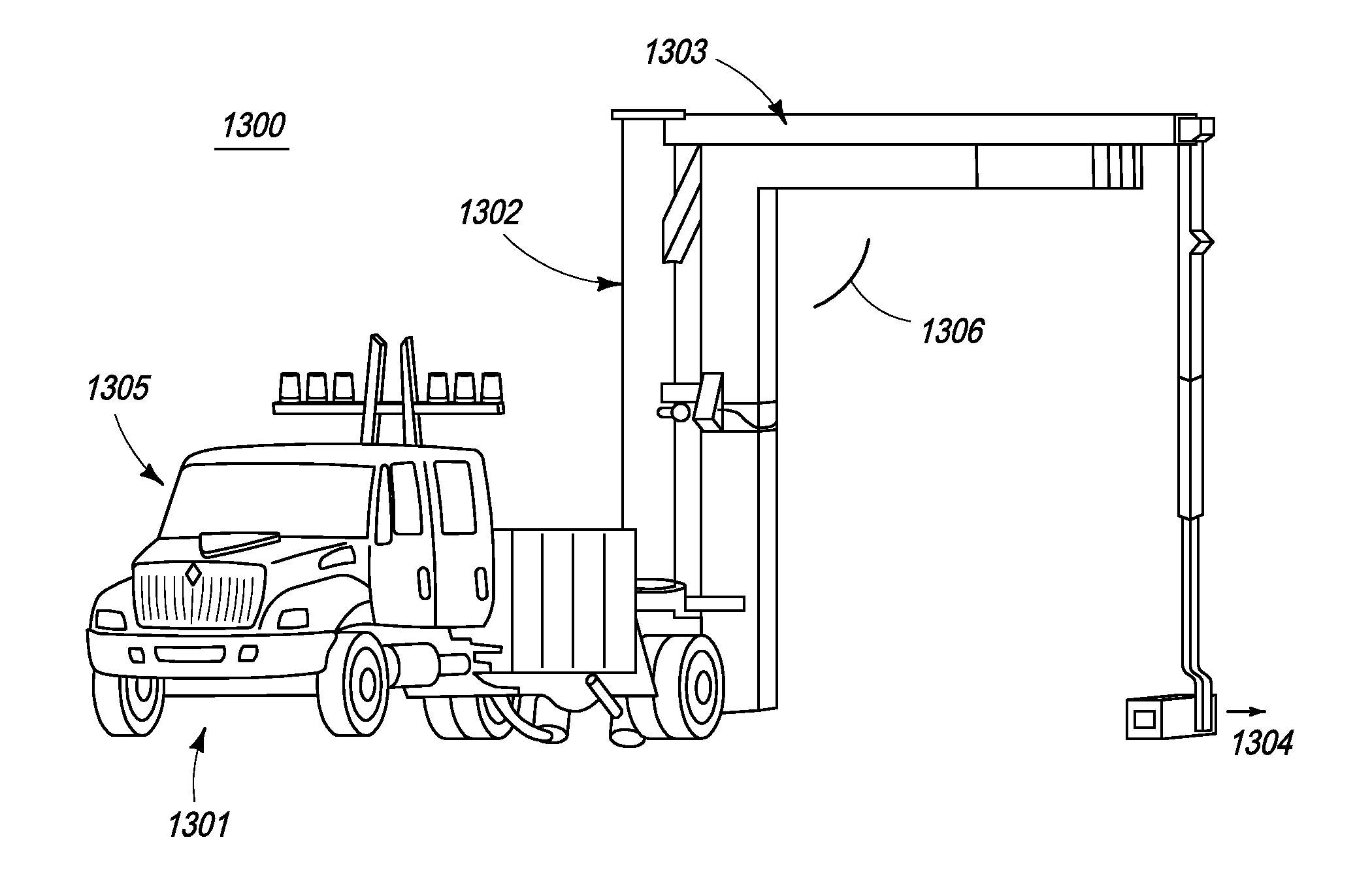
[0144]In a second embodiment, the present invention is directed towards a relocatable cargo inspection system that employs a single boom attached to a truck that is capable of receiving and deploying the boom. The boom comprises a plurality of radiation detectors and a source. The boom is preferably installed in the rear of the truck to minimize radiation dosage to the driver and is capable of being folded into the truck and folded out, thus forming an inverted “L” on either the driver or passenger side.

[0145]The single boom structure permits the source, positioned at the base of the connecting structure, to rigidly align with the detector array, also permitting the unit to operate with a narrower beam width and a lower radiation level. In addition, the position of the source at the base of the connecting structure enables a larger field of view relative to conventional systems having the source on the vehicle. The source preferably extends to a height as low as six inches off the g...


PUM

PropertyMeasurementUnit
angleaaaaaaaaaa
angleaaaaaaaaaa
optimal offset distanceaaaaaaaaaa

Abstract

The present invention is directed to a portable inspection system for generating an image representation of target objects using a radiation source. A detector array having a first configuration and a second configuration is connected to a housing and at least one source of radiation. The radiation source is capable of being transported to a site by a vehicle and of being positioned separate from the housing. The radiation source is housed in a radiation source box and movable within the radiation source box using an actuator. The actuator is operably connected to the radiation source and provides a translational energy that moves the radiation source between an operational position and a stowed position.

Description

CROSS-REFERENCE TO RELATED APPLICATIONS[0001]The present invention relies on, for priority, U.S. Provisional Patent Application No. 60 / 984,786, entitled “Cargo Scanning System” and filed on Nov. 2, 2007. In addition, the present invention is a continuation-in-part of U.S. patent application Ser. No. 11 / 948,814, entitled, “Single Boom Cargo Scanning System”, filed on Nov. 30, 2007 now U.S. Pat. No. 7,517,149, which is a continuation of U.S. patent application Ser. No. 10 / 915,687, now U.S. Pat. No. 7,322,745, entitled, “Single Boom Cargo Scanning System”, filed on Aug. 9, 2004, which further relies on, for priority, U.S. Provisional Patent Application No. 60 / 493,935, filed on Aug. 8, 2003. U.S. patent application Ser. No. 10 / 915,687 is a continuation-in-part of U.S. patent application Ser. No. 10 / 201,543, entitled “Self-Contained Portable Inspection System and Method”, filed on Jul. 23, 2002 and now U.S. Pat. No. 6,843,599. All of the aforementioned applications and patents are incorp...

Claims


Application Information

Patent Timeline
Patent Type & Authority Patents(United States)
IPC IPC(8): G01N23/04
CPCG01N23/04G01V5/0008H05G1/02G01N2223/639
Inventor KOTOWSKI, ANDREASAGRAWAL, NEERAJ
Owner RAPISCAN SYST INC (US)
Why Eureka
Try Eureka