Movable siderail apparatus for use with a patient support apparatus

a technology for supporting devices and siderails, which is applied in the direction of fluid mattresses, sofas, transportation and packaging, etc., can solve the problems of pinch points between the siderails and the arms, and safety problems for the patient or other person operating the siderail

Active Publication Date: 2010-08-31
STRYKER CORP
View PDF12 Cites 56 Cited by
  • Summary
  • Abstract
  • Description
  • Claims
  • Application Information

AI Technical Summary

Problems solved by technology

This design however, has pinch points between the siderails and the arms when the siderails are moved from the raised position to the lowered position, especially when operated by a caregiver or someone located on the side of the bed.
This siderail design however creates pinch points between the siderails and the arms when the siderails are moved from the raised position to the lowered position, especially when operated by a caregiver or someone located on the side of the bed.
Similarly to the siderail designs discussed above, this mechanism can create several pinch points between the siderails and the arms when the siderails are moved from the raised position to the lowered position, creating a safety problem for the patient or other person operating the siderail.
Based on the current state of the art, there are several problems with the siderail apparatuses used in beds or the like.
For example, a problem arising from the existing siderail mechanisms used in medical beds which allow any lateral movement is that typically there is a multiple step operation of the siderail to move it from a raised position to a lowered position.
This process requires time, effort and is inefficient.
Some of the actions associated with the operation of such a device often require actions that are not ergonomic for the exertion of a significant level of effort.
Another problem arising out of the prior art related to a bed siderail is the space required for the operation of the siderail.
Various existing products require significant lateral space to operate the siderail.
Furthermore, the operation may require the user of the siderail mechanism to move away from the bed in order to raise or lower the siderail and in some cases the user has to move the entire bed to an area with sufficient space before operating the siderail.
This is a significant problem since the space in medical facilities is often limited, there are unnecessary efforts and unnecessary movement of the patient involved and requires more time to accomplish the desired function, thereby diminishing time for a health worker to dispense medical services.
A further problem with the existing siderail mechanisms and the prior art using a “clock-type” movement in a vertical plane parallel to the length of the bed is the creation of pinch points during the operation of the siderail.
When such siderails are moved, angles between the support arms and the bottom-most edge of the siderail become acute thereby creating a pinch point where fingers, hands, clothing or bed sheets can get caught and cause injuries to the user and / or patient or create malfunctions of the siderail mechanism.

Method used


Image

  • Movable siderail apparatus for use with a patient support apparatus
  • Movable siderail apparatus for use with a patient support apparatus
  • Movable siderail apparatus for use with a patient support apparatus

Examples


Embodiment Construction

Definitions

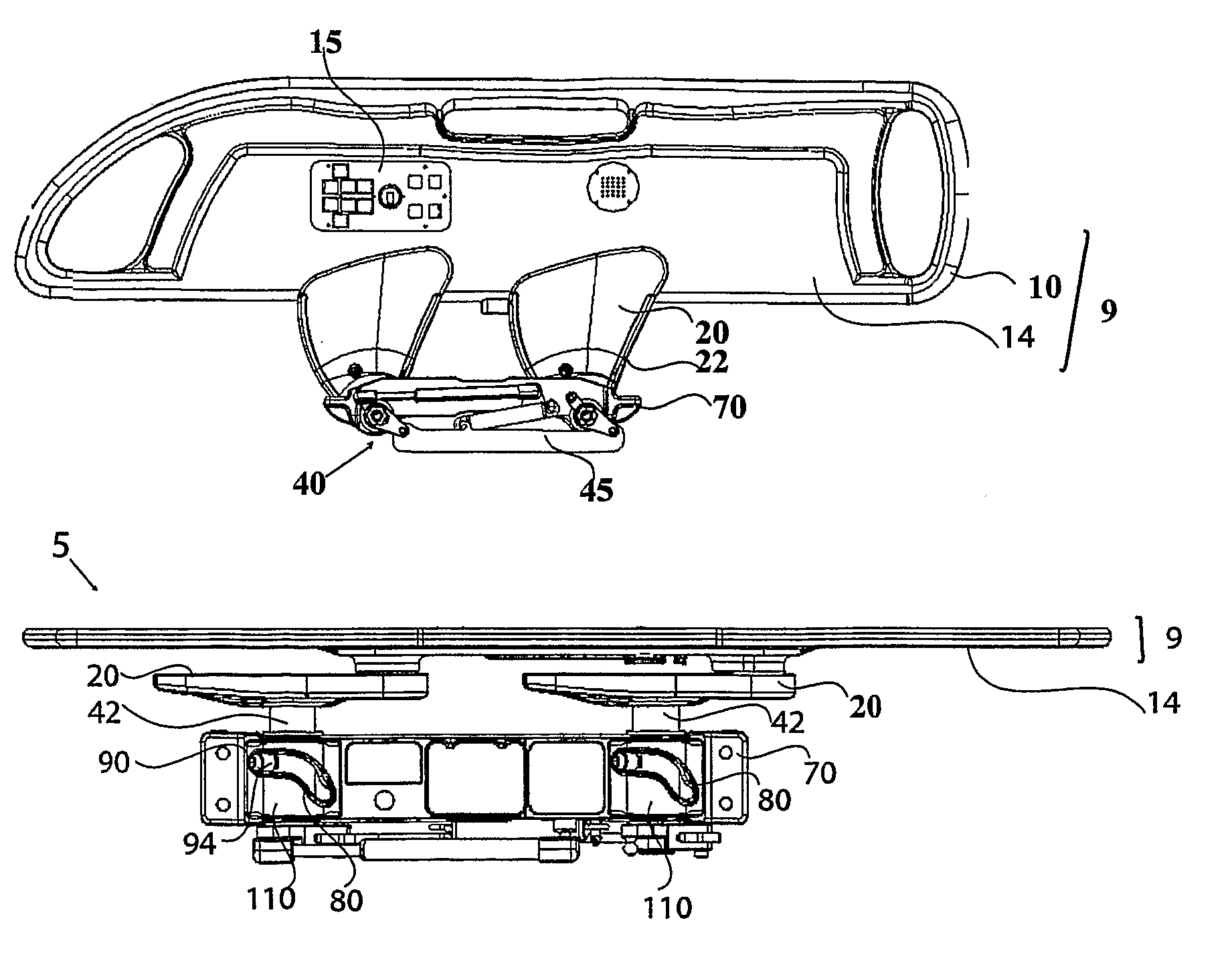
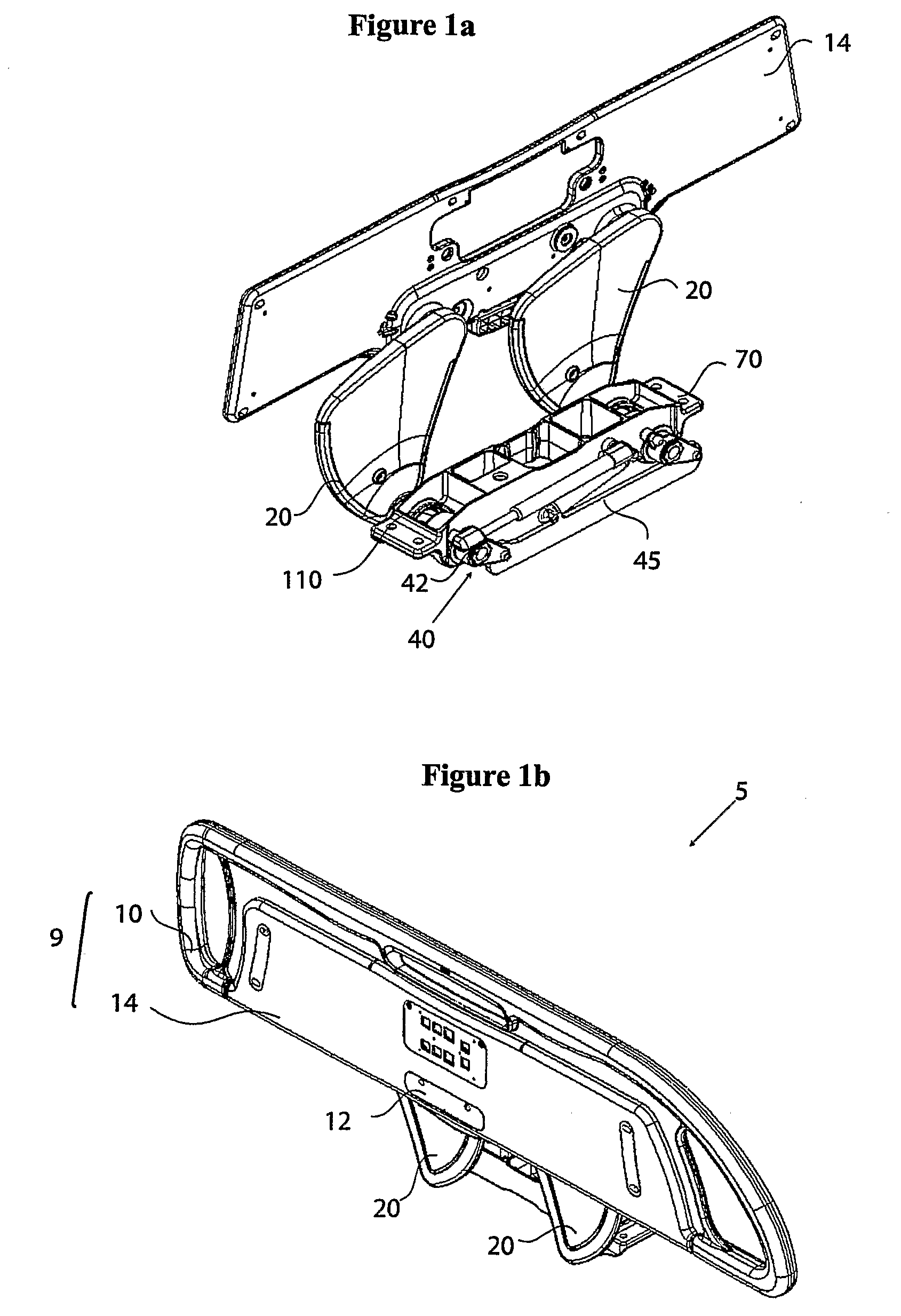
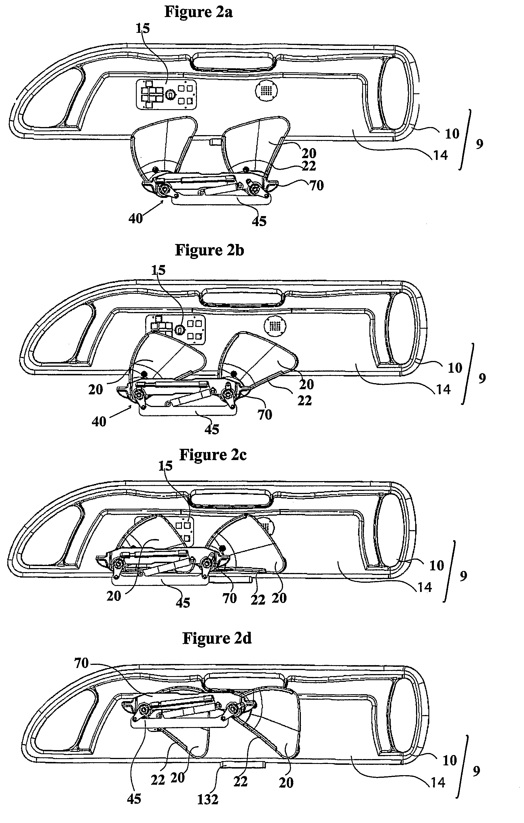
[0100]The term “siderail” is used to define the part of a siderail apparatus designed to secure the lying surface to ensure the patient does not fall from or exit the lying surface when the siderail apparatus is in its fully or partially deployed positions.

[0101]The term “locking mechanism” is used to define any mechanism configured to allow the siderail apparatus to be locked or unlocked in any predetermined position.

[0102]The term “support arms” is used to define the physical components connecting the siderail body to the mechanism casing through pivots situated in proximity of each end of each of said support arms.

[0103]The term “guiding mechanism” is used to define a means for guiding the siderail body through a lateral movement of the siderail body towards and away from the lying surface during rotational movement of the siderail body.

[0104]The term “inside view” is used to define a view in relation to the siderail apparatus means the view from the side in relative p...


PUM


Abstract

The present invention provides a movable siderail apparatus (5) for use with a patient support apparatus. The siderail apparatus (5) is configured to move the siderail body (14) associated therewith in a clock-type swing movement relative to the patient support apparatus. Two or more support arms (20) are disposed between the intermediate frame or the deck support of the patient support apparatus and the siderail body (14), each support arm (20) having two pivots (30, 40), a first (40) rotatably connecting it to the intermediate frame or deck support and a second (30) rotatably connecting it to the siderail body (14), thereby enabling the siderail body (14) to be raised or lowered vertically by a rotation substantially parallel to the longitudinal direction of the patient support apparatus. In a first preferred embodiment, the angles defined between each support arm (20) and a lower edge of the siderail (9) are substantially obtuse during rotational movement of the siderail (9). In a second preferred embodiment, a guiding mechanism (110) is operatively connected to the cross-member (70) and two or more lower pivots (40), such that the guiding mechanism (110) provides means for lateral movement of the siderail (9) toward and away from the support apparatus.

Description

FIELD OF THE INVENTION[0001]The present invention pertains to the field of siderail apparatuses and in particular to a siderail apparatus for use with a patient support apparatus.BACKGROUND OF THE INVENTION[0002]Siderail apparatuses have been widely used in various applications such as with hospital beds, stretchers and other lying surfaces used in medical applications. One of the main purposes of a siderail apparatus in such applications is to secure the patient on the lying surface by diminishing the possibility of the patient accidentally falling off of the lying surface or in some case to prevent the patient from intentionally leaving the lying surface.[0003]Most siderail apparatuses are moveable in one-way or another. This characteristic improves the flexibility and the ease of use of a siderail apparatus in various ways. The main moving feature of a siderail apparatus is the ability to move the siderail to a deployed position when patient security is needed and to a stowed pos...

Claims


Application Information

Patent Timeline
Patent Type & Authority Patents(United States)
IPC IPC(8): A47C21/08
CPCA61G7/0507A61G2203/42A61G2007/0516A61G2007/0509A61G7/0509A61G7/0516
Inventor MORIN, MARCOCASTONGUAY, PASCALLEMIRE, GUYDIONNE, JEAN-PAUL
Owner STRYKER CORP
Why Eureka
Try Eureka