Cap assembly of a fastener-driving tool having switch mechanism incorporated therein for switching modes of operation of the fastener-driving tool

a technology of fastener-driving tools and switch mechanisms, which is applied in the field of new and improved cap assemblies of fastener-driving tools with a new and improved switch mechanism incorporated, which can solve the problem that conventional fastener-driving tools do not have incorporated therewithin a simple mechanism

Inactive Publication Date: 2010-08-31
ILLINOIS TOOL WORKS INC
View PDF77 Cites 8 Cited by
  • Summary
  • Abstract
  • Description
  • Claims
  • Application Information

AI Technical Summary

Problems solved by technology

Unfortunately, conventional fastener-driving tools do not have incorporated therewithin a simple mechanism for effectively altering the mode of operation of the fastener-driving tool between, for example, either one of the first or second single-shot firing modes of operation and the third fully automatic continuous firing mode of operation.

Method used


Image

  • Cap assembly of a fastener-driving tool having switch mechanism incorporated therein for switching modes of operation of the fastener-driving tool
  • Cap assembly of a fastener-driving tool having switch mechanism incorporated therein for switching modes of operation of the fastener-driving tool
  • Cap assembly of a fastener-driving tool having switch mechanism incorporated therein for switching modes of operation of the fastener-driving tool

Examples


Embodiment Construction

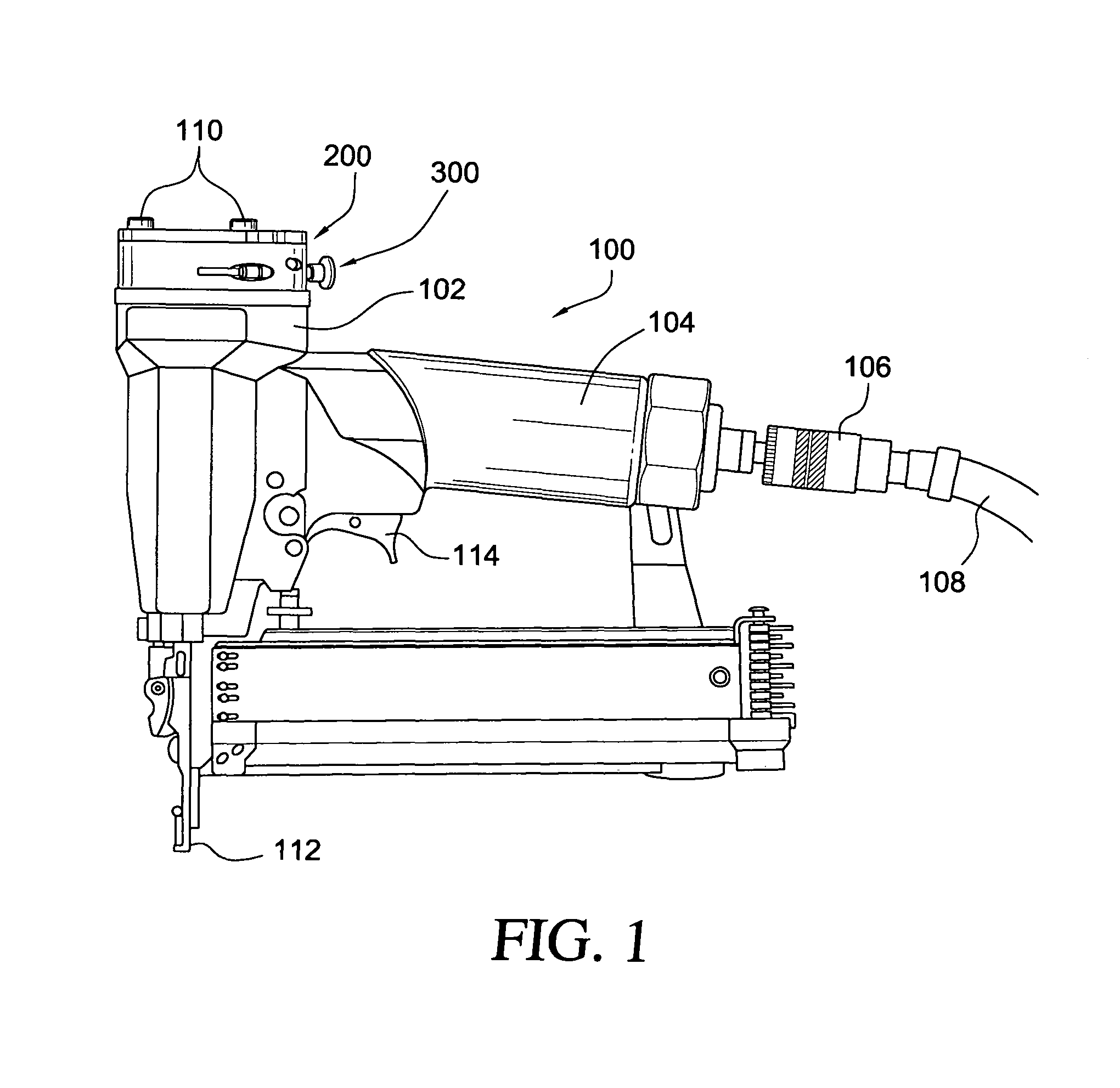
[0014]Referring now to the drawings, and more particularly to FIG. 1 thereof, the upper end portion of a new and improved fastener-driving tool is disclosed and is generally indicated by the reference character 100. More particularly, the fastener-driving tool 100 is seen to comprise an upper housing portion 102 within which there is defined a cylinder, not shown, in which there is disposed a working piston, also not shown, having a driver blade mechanism or the like, also not shown, which is conventionally used to drive a fastener out from the fastener-driving tool 100 and into a workpiece or substrate. The upper housing portion 102 has a handle member 104 integrally formed or connected thereto, and a compressed air connector 106 is operatively connected to the handle member 104 so as to operatively and fluidically attach a compressed air line 108, leading from a suitable source of compressed air, not shown, to the fastener-driving tool 100.

[0015]In addition, it is also seen that, ...


PUM

PropertyMeasurementUnit
speedaaaaaaaaaa
flexibleaaaaaaaaaa
pressureaaaaaaaaaa

Abstract

A fastener-driving tool is provided with a cap assembly which includes a switch mechanism that permits the tool to be operated in one of two firing modes of operation. The switch mechanism comprises a two-position switch mechanism such that when the switch mechanism is disposed at a first one of its two positions, the tool will be able to operate in a fully automatic continuous firing mode of operation so as to continuously fire fasteners into a substrate as long as the workpiece contact element and the trigger mechanism are disposed at their depressed positions, or alternatively, when the switch mechanism is disposed at the second one of the two positions, the tool can be operated in a one-shot firing mode such that the tool can only fire a single fastener, either in accordance with, for example, a sequential-firing mode of operation or a bump-firing mode of operation, until the trigger mechanism is released and again depressed.

Description

FIELD OF THE INVENTION[0001]The present invention relates generally to fastener-driving tools, and more particularly to a new and improved cap assembly of a fastener-driving tool having a new and improved switch mechanism incorporated therein wherein, for example, the new and improved switch mechanism comprises a two-position switch mechanism whereby when the switch mechanism is disposed at a first one of the two positions, the fastener-driving tool can be operated in a fully automatic continuous firing mode of operation by means of which the fastener-driving tool can continuously fire fasteners into a substrate or workpiece as long as the workpiece contact element is maintained at its engaged or depressed position against the workpiece or substrate, and as long as the trigger mechanism is likewise maintained at its actuated or depressed position, or alternatively, when the switch mechanism is disposed at a second one of the two positions, the fastener-driving tool can be operated i...

Claims


Application Information

Patent Timeline
Patent Type & Authority Patents(United States)
IPC IPC(8): B25C1/04
CPCB25C1/047
Inventor MINA, NATHAN T.CORTEZ, GENARO
Owner ILLINOIS TOOL WORKS INC
Why Eureka
Try Eureka