Liquid crystal display apparatus

a technology of liquid crystal display and display apparatus, which is applied in the direction of static indicating devices, instruments, non-linear optics, etc., can solve the problem of no suggestions, and achieve the effect of good bright display state and free from unevenness

Inactive Publication Date: 2010-08-31
SAMSUNG ELECTRONICS CO LTD
View PDF12 Cites 116 Cited by
  • Summary
  • Abstract
  • Description
  • Claims
  • Application Information

AI Technical Summary

Benefits of technology

[0008]Accordingly, it is an object of the present invention to provide a transflective liquid crystal display apparatus in which the polarizer, the reflective polarizer, and the liquid crystal molecules in the liquid crystal are oriented or aligned properly.
[0029]Furthermore, according to the present invention, in the transflective liquid crystal display apparatus using the memory liquid crystal, a good bright display state free from unevenness can be achieved in applications where the display is normally produced in the reflective mode that does not use the auxiliary light source.

Problems solved by technology

However, in the transflective liquid crystal display apparatus, no suggestions have been made as to how the polarizer, the reflective polarizer, and the liquid crystal molecules in the liquid crystal should be oriented or aligned, according to purpose.

Method used


Image

  • Liquid crystal display apparatus
  • Liquid crystal display apparatus
  • Liquid crystal display apparatus

Examples


first embodiment

[0048]A first embodiment will be described.

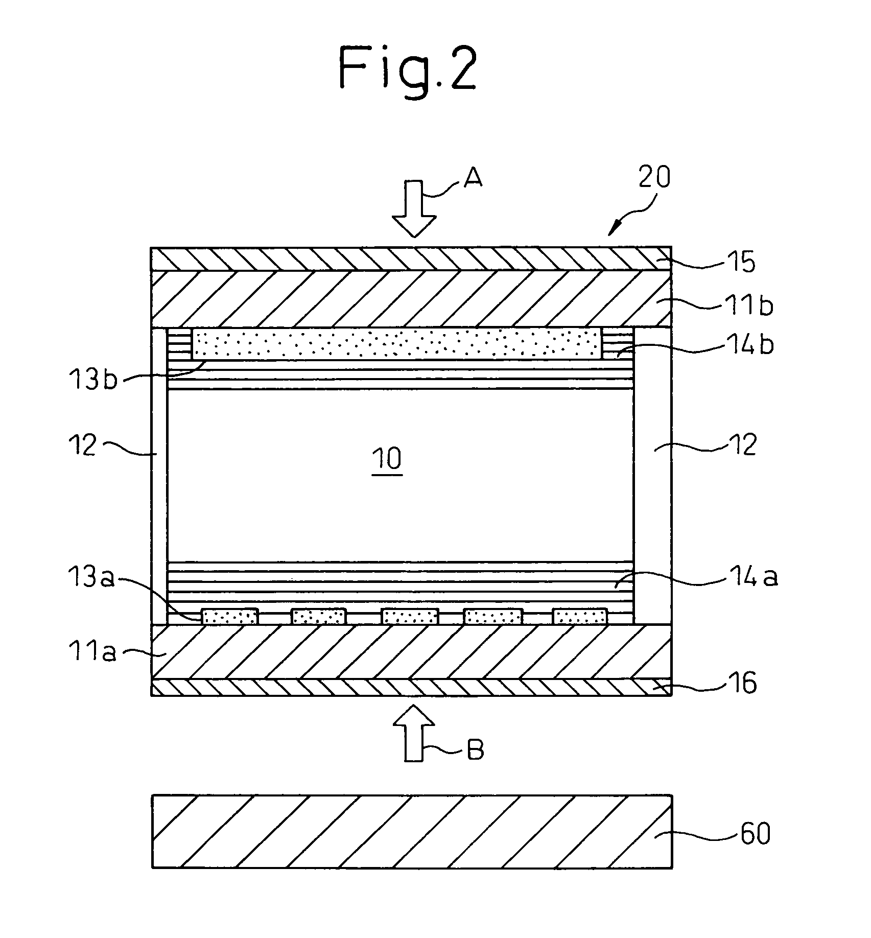
[0049]FIG. 2 shows a cross-sectional view of the liquid crystal panel 20 according to the first embodiment, along with the auxiliary light source 60.

[0050]The liquid crystal panel 20 according to the first embodiment includes a first transparent glass substrate 11a, a second transparent glass substrate 11b, scanning electrodes 13a formed on the first transparent glass substrate 11a, signal electrodes 13b formed on the second transparent glass substrate 11b, a polymeric alignment film 14a deposited over the scanning electrodes 13a and treated by rubbing, a polymeric alignment film 14b deposited over the signal electrodes 13b and treated by rubbing, a sealing member 12, a ferroelectric liquid crystal 10 provided between the first and second transparent substrates 11a and 11b and sealed by the sealing member 12, a reflective polarizer 16 provided on the outer side of the first transparent substrate 11a, and a polarizer 15 provided on the outer...

second embodiment

[0090]A second embodiment will be described.

[0091]The cross-sectional structure of the liquid crystal panel 20 according to the second embodiment and the structure of the auxiliary light source 60 are the same as those shown in FIG. 2, and a description thereof will not be repeated here.

[0092]In the second embodiment also, “FELIX 501” manufactured by Clariant is used as the ferroelectric liquid crystal 10. Further, in the second embodiment also, the gap between the first and second transparent glass substrates 11a and 11b is set to approximately 1.7 μm.

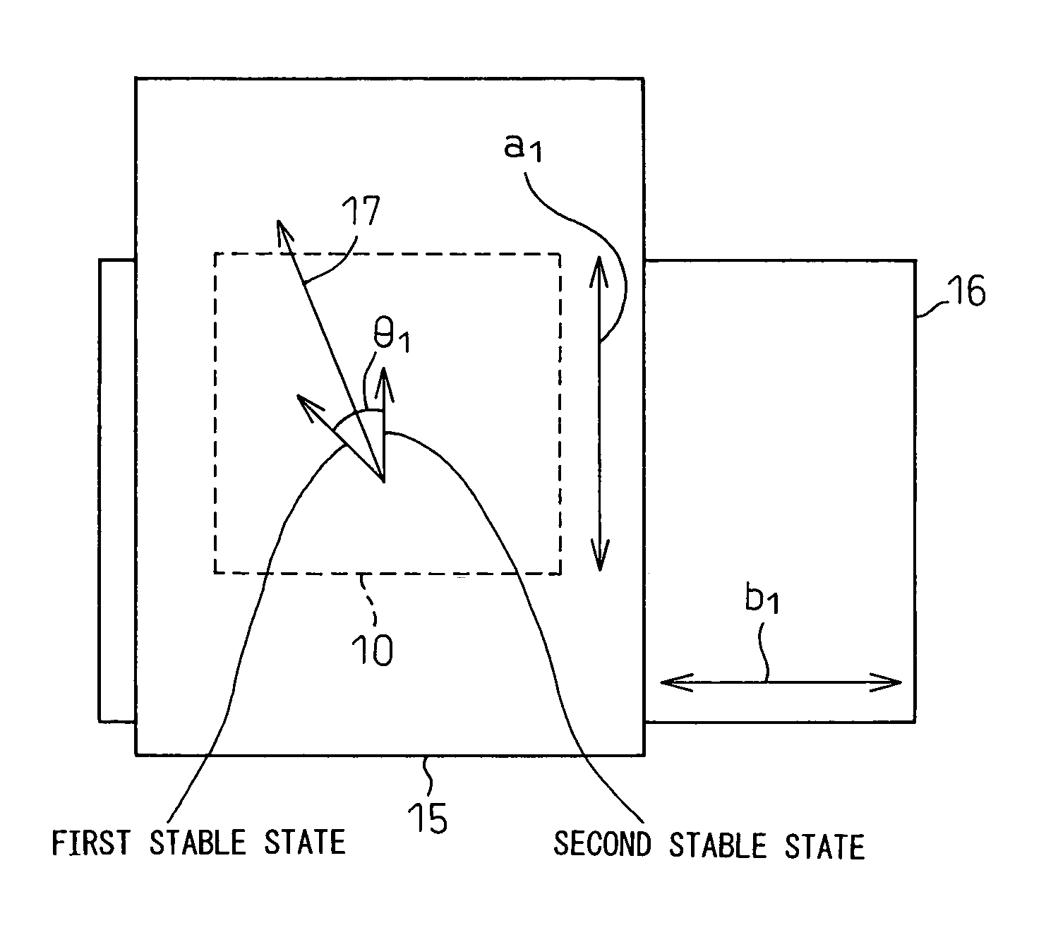
[0093]FIG. 8 shows the arrangement of the polarizer 15 and the reflective polarizer 16 in the liquid crystal panel 20 according to the second embodiment.

[0094]As shown in FIG. 8, the transmission axis (a2) of the polarizer 15 is oriented in parallel to the transmission axis (b2) of the reflective polarizer 16. In FIG. 8, the ferroelectric liquid crystal 10 is arranged so that, in the second stable state, the long axes of the liquid cr...

third embodiment

[0120]A third embodiment will be described.

[0121]The third embodiment will be described with reference to FIG. 2. Substantially the same structure as that shown in FIG. 2 can be used in the third embodiment. However, the scanning electrodes 13a and the signal electrodes 13b are coated with polymeric alignment films 14a and 14b, respectively, treated for vertical alignment. Further, MLC-6883 (manufactured by Merck), a liquid crystal material having a negative dielectric anisotropy, is used as a liquid crystal 110 which is a vertically aligned (homeotropically aligned) liquid crystal. The liquid crystal 110 sandwiched between the first and second transparent glass substrates 11a and 11b is about 1.7 μm in thickness.

[0122]In FIG. 2, arrow A indicates ambient light incident on the liquid crystal panel of the third embodiment from the outside, and arrow B shows light incident on the liquid crystal panel of the third embodiment from the auxiliary light source 60.

[0123]FIG. 10 shows the ar...


PUM

PropertyMeasurementUnit
thicknessaaaaaaaaaa
cone angleaaaaaaaaaa
angleaaaaaaaaaa

Abstract

The liquid crystal display apparatus according to the present invention includes a first substrate, a second substrate, a reflective polarizer, mounted on the first substrate and having a first transmission axis and a first reflection axis at right angles to each other, for transmitting linearly polarized light vibrating in a plane parallel to the first transmission axis and for reflecting linearly polarized light vibrating in a plane parallel to the first reflection axis, a polarizer, mounted on the second substrate and having a second transmission axis, for transmitting linearly polarized light vibrating in a plane parallel to the second transmission axis, and a liquid crystal layer, provided between the first and second substrates, having a first mode which causes the direction of polarization of incident light to change by utilizing birefringence and a second mode which does not utilize birefringence and therefore does not cause the direction of polarization of incident light to change, wherein a display state is switched between a bright display state and a dark display state by applying a voltage to the liquid crystal layer, and the bright display state is produced by driving the liquid crystal layer in the second mode.

Description

FIELD OF THE INVENTION[0001]The present invention relates to a liquid crystal display apparatus and, more particularly, to a liquid crystal display apparatus that can display a background in a bright state without utilizing birefringence.BACKGROUND OF THE INVENTION[0002]A memory liquid crystal, which is capable of exhibiting a plurality of optical states, has a characteristic (a memory characteristic) such that it continues to retain a particular state even if a voltage is not applied to it. When such a memory liquid crystal is used in a liquid crystal display apparatus, the apparatus can be controlled to continue to display a particular image without requiring application of a voltage. In a display panel using a memory liquid crystal such as a ferroelectric liquid crystal, it is know to utilize the memory characteristic and perform control in such a manner as to drive scanning electrodes only for portions where the display needs to be updated but not to drive scanning electrodes fo...

Claims


Application Information

Patent Timeline
Patent Type & Authority Patents(United States)
IPC IPC(8): G02F1/1339
CPCG02F1/1393G09G3/36G02F1/133536G02F2203/02G02F2203/64G02F2203/66G09G2300/0491
Inventor KONDOH, SHINYAOHARA, MIE
Owner SAMSUNG ELECTRONICS CO LTD
Why Eureka
Try Eureka