

Communication device, communication system, communication method, communication program, and communication circuit
a communication device and communication system technology, applied in the field of communication devices, can solve the problems of increasing device cost, development difficulty, and difficulty in changing device specifications
- Summary
- Abstract
- Description
- Claims
- Application Information
AI Technical Summary
Benefits of technology
Problems solved by technology
Method used
Image

Examples
embodiment 1
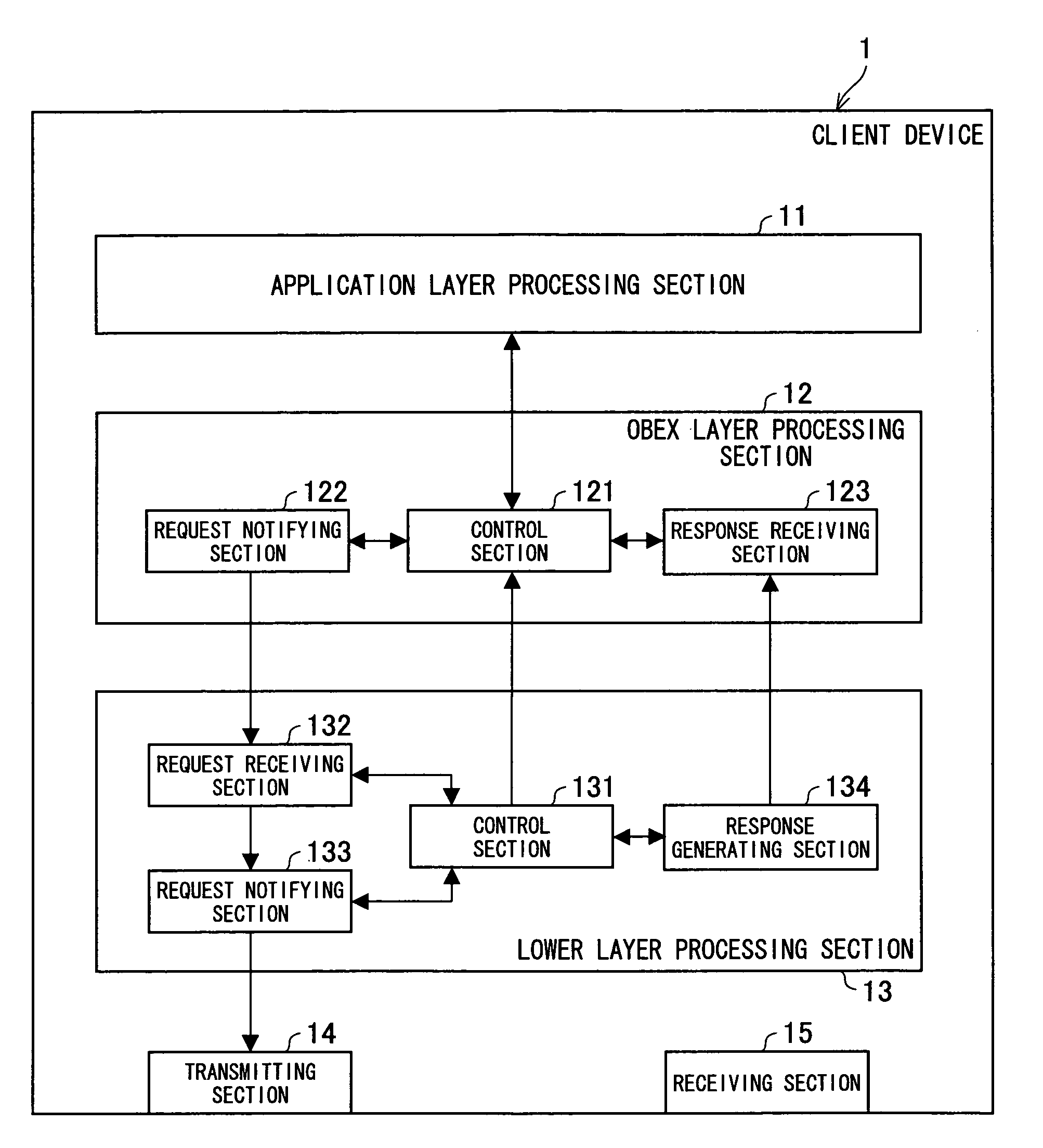
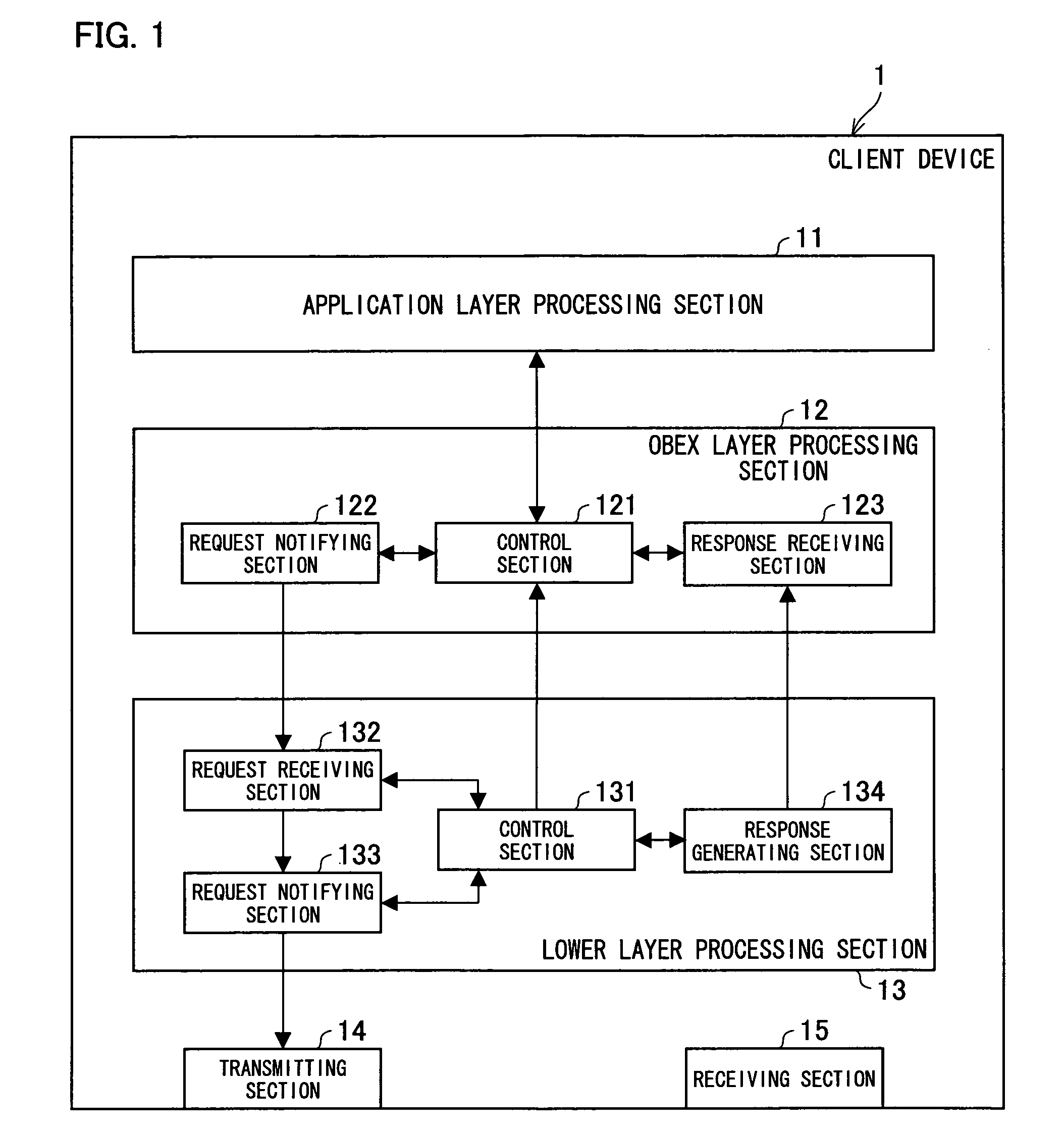
[0229]A client device 1 serving as Embodiment 1 according to the present invention will be explained below with reference to FIG. 1. Note that wordings (inclusive of a member and a function) defined in the other embodiments are used in the same manner in the present embodiment, unless otherwise noted.
[0230]FIG. 1 is a block diagram illustrating a structure of the client device 1 of a communication system according to the present embodiment. As shown in FIG. 1, the client device 1 includes an application layer processing section 11, an OBEX layer processing section (object exchange layer processing section) 12, a lower layer processing section 13, a transmitting section 14, and a receiving section 15. The application layer processing section 11, the OBEX layer processing section 12, and the lower layer processing section 13 are provided in this order from top to bottom, thereby constituting a hierarchical structure. The application layer processing section 11, the OBEX layer processi...
embodiment 2
[0294]The following explains a client device (communication device) of a data transferring system (communication system) according to Embodiment 2 of the present invention, with reference to FIG. 5. Note that wordings (inclusive of a member and a function) defined in the other embodiments are used in the same manner in the present embodiment, unless otherwise noted.
[0295]FIG. 5 is a block diagram illustrating a structure of the client device of the present embodiment. As shown in FIG. 5, such a client device 2 includes an application layer processing section 21, an OBEX layer processing section (object exchange layer processing section) 22, a lower layer processing section 23, a transmitting section 24, and a receiving section 25, which have the same functions as those of the client device 1 shown in FIG. 1, respectively.
[0296]In response to a user's instruction inputted via an operation section (not shown), the application layer processing section 21 requests the OBEX layer process...
embodiment 3
[0324]The following explains a client device (communication device) of a data transferring system (communication system) according to Embodiment 3 of the present invention, with reference to FIG. 10. Note that wordings (inclusive of a member and a function) defined in the other embodiments are used in the same manner in the present embodiment, unless otherwise noted.
[0325]FIG. 10 is a block diagram illustrating a structure of the client device of the present embodiment. As shown in FIG. 10, such a client device 3 includes an application layer processing section 31, an OBEX layer processing section (object exchange layer processing section) 32, a lower layer processing section 33, a transmitting section 34, and a receiving section 35, which have the same functions as those of the client device 1 shown in FIG. 1, respectively.
[0326]In response to a user's instruction inputted via an operation section (not shown), the application layer processing section 31 requests the OBEX layer proc...
PUM
 Abstract
Description
Claims
Application Information