Method enabling dual pressure control within fiber preform during fiber fabrication

a technology of fiber preform and fiber preform, which is applied in the field of fabricating a photonic crystal optical fiber or can solve the problems of difficult reproduction of the manufacturing process used to manufacture hollow-core microstructured optical fibers, significant effect on attenuation behavior, and distortion of hollow-core photonic band gap fibers. achieve the effect of reducing time, expense and complexity of the process, and facilitating close control of the hole siz

Active Publication Date: 2010-09-14
CORNING INC
View PDF21 Cites 25 Cited by
  • Summary
  • Abstract
  • Description
  • Claims
  • Application Information

AI Technical Summary

Benefits of technology

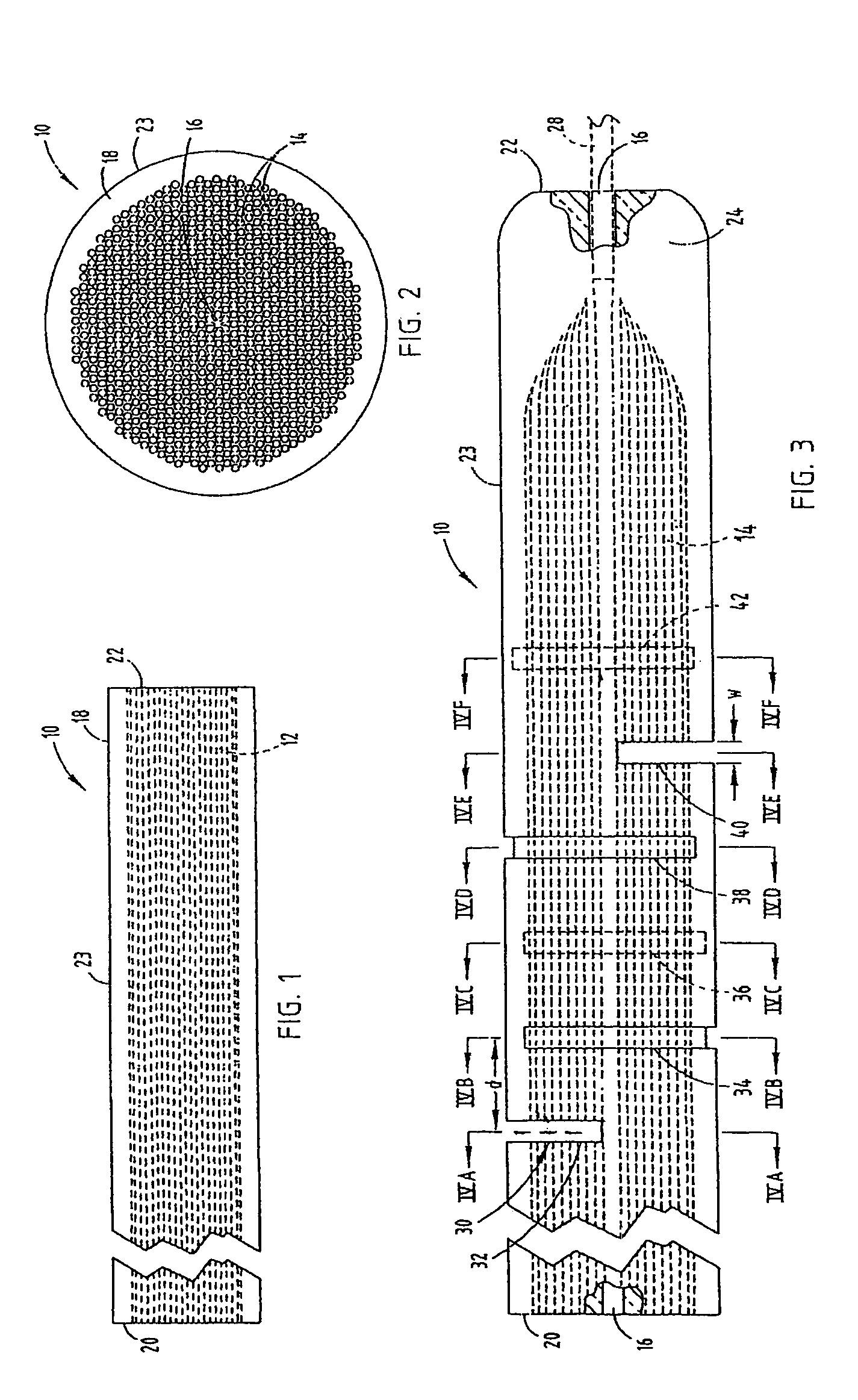
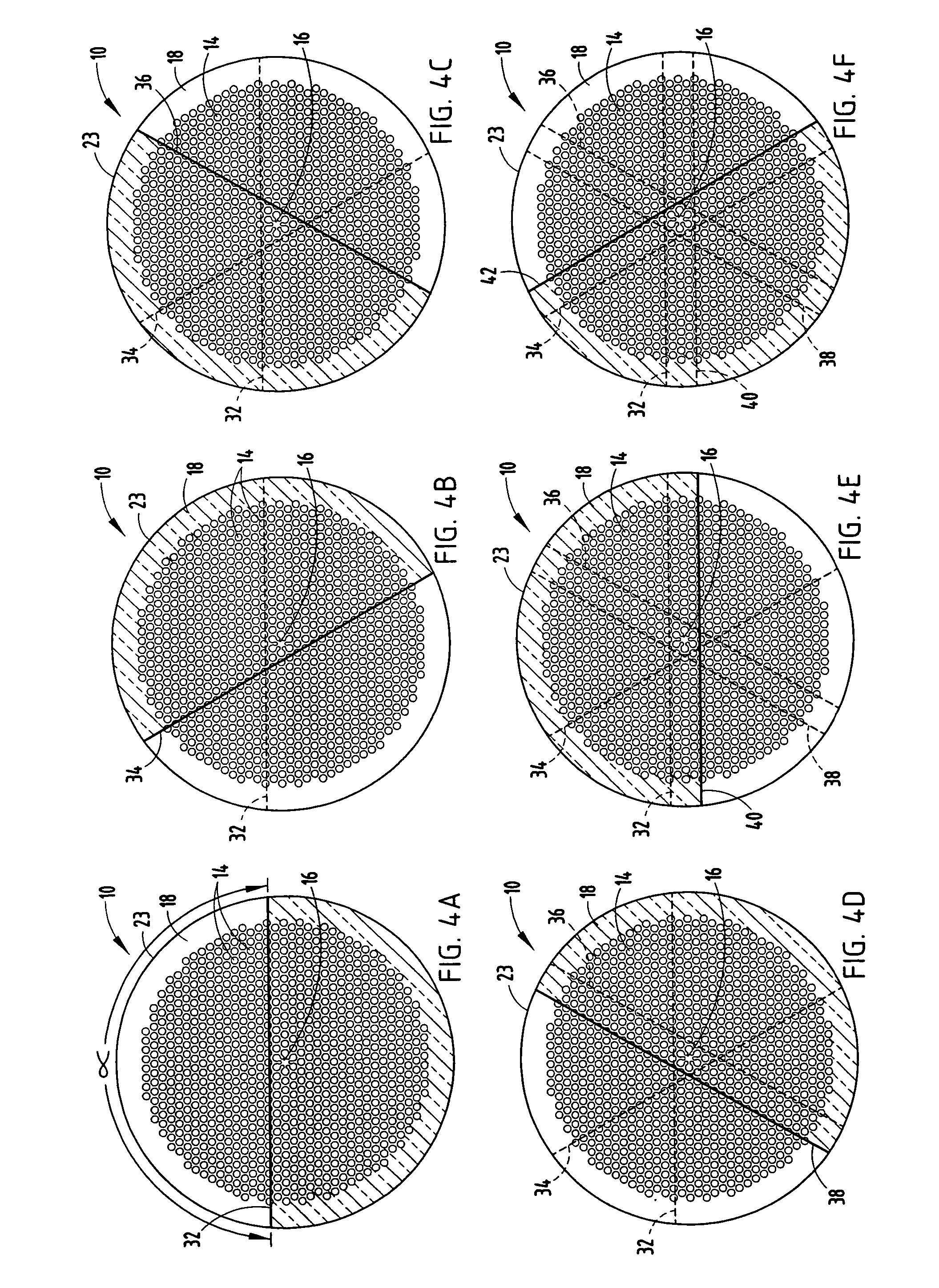
[0011]Another aspect of the present invention relates to a method of fabricating a photonic crystal or photonic band gap optical fiber, wherein the method comprises providing a plurality of elongate glass tubes, each having a longitudinal axis, a first end and a second end, at least some of the glass tubes being capillaries each having a hole parallel to the longitudinal axis of the glass tube and running from the first end of the glass tube to the second end of the glass tube, forming the glass tubes into a stack, the glass tubes being arranged such that the longitudinal axis of each of the glass tubes is substantially parallel to one another, and heating and reducing the diameter (i.e., drawing) the stack to form a preform, wherein the preform has a first end and a second end. The method may also comprise closing at least some of the holes of the preform at the first end of the preform by heating and deforming a first end of the preform, and forming a plurality of radially inwardly extending and longitudinally spaced slots within the preform such that each of the slots intersects some of the holes, thereby providing pneumatic communication between the outer surface of the preform and the holes, wherein the slots do not intersect all of the glass holes. The method further comprises securing a first tube to the first end of the preform such that the first tube is in pneumatic communication with at least some of the holes of the preform not intersected by the slots, and securing a second tube about the outer surface of the preform such that the second tube is in pneumatic communication with the slots. The method still further comprises establishing a first pressure in the holes intersected by the slots by introducing the first pressure to the slots through the second tube, establishing a second pressure in the holes of the glass tubes not intersected by the slots by introducing a second pressure through the first tube, and drawing the preform into a fiber while independently controlling the first and second pressures. This independent control of the first and second pressures facilitates close control of the hole size, pitch, core size and the shape of the core.
[0012]The present inventive methods disclosed herein allow practical, robust and repeatable solutions for manufacturing hollow-core microstructured optical fibers. These methods reduce the time, expense and complexity of the process normally associated with the manufacture of hollow-core microstructured optical fibers and are particularly well suited for the proposed use.

Problems solved by technology

Such distortions are especially damaging in hollow-core photonic band gap fibers, as the band gap may be quite sensitive to variations in characteristic dimensions of the photonic crystal structure such as hole size, pitch and symmetry.
Such distortions can also affect the geometry of the core / cladding boundary which can in turn have a significant effect on the attenuation behavior of the guided mode.
Heretofore, the manufacturing process utilized to manufacture hollow-core microstructured optical fibers have been difficult to reproduce, relatively expensive, and time consuming.

Method used


Image

  • Method enabling dual pressure control within fiber preform during fiber fabrication
  • Method enabling dual pressure control within fiber preform during fiber fabrication
  • Method enabling dual pressure control within fiber preform during fiber fabrication

Examples


Embodiment Construction

[0023]For purposes of description herein, the terms “upper,”“lower,”“right,”“left,”“rear,”“front,”“vertical,”“horizontal,” and derivatives thereof shall relate to the invention as oriented in FIGS. 1, 3 and 5. However, it is to be understood that the invention may assume various alternative orientations and step sequences, except where expressly specified to the contrary. It is also to be understood that the specific devices and processes illustrated in the attached drawings, and described in the following specification are exemplary embodiments of the inventive concepts defined in the appended claims. Hence, specific dimensions and other physical characteristics relating to the embodiments disclosed herein are not to be considered as limiting, unless the claims expressly state otherwise.

[0024]In one aspect of the present invention, a method for forming a microstructured optical fiber is provided. In this method, a preform having a plurality of holes and an outer surface is provided...


PUM

PropertyMeasurementUnit
lengthaaaaaaaaaa
distanceaaaaaaaaaa
diameteraaaaaaaaaa

Abstract

A method of fabricating a photonic crystal or photonic band gap optical fiber comprises providing a preform that includes a plurality of holes in an outer diameter, wherein the holes extend from a first end of a preform to a second end of the preform, and forming at least one radially inwardly-extending slot within the preform such that the slot intersects at least some of the holes, wherein the slot does not intersect at least one hole. The method also includes establishing a first pressure in the holes intersected by the slot by introducing the first pressure to the slot, and establishing a second pressure in the at least one hole not intersected by the slot by introducing the second pressure to an end of the at least one hole not intersected by the slot. The method further includes drawing the preform into a fiber while independently controlling the first and second pressures.

Description

BACKGROUND OF THE INVENTION[0001]1. Field of the Invention[0002]The invention is directed to a method of fabricating a photonic crystal optical fiber or photonic band gap fiber, and in particular to a method providing independent control of pressures within a plurality of longitudinally-extending holes within a preform during the draw of the preform into the optical fiber.[0003]2. Technical Background[0004]Optic fibers are used in a wide variety of fields, including telecommunications, laser machining and welding, laser beam and power delivery, fiber lasers, etc. Typically, fibers are constructed from solid transparent materials such as glass and have a similar cross-sectional configuration along the length thereof. An alternative design to such fibers includes a microstructured optical fiber having holes or voids running longitudinally along the fiber axis. These holes generally contain air or an inert gas, but may also contain other materials.[0005]Microstructured optical fibers m...

Claims


Application Information

Patent Timeline
Patent Type & Authority Patents(United States)
IPC IPC(8): C03B37/023
CPCC03B37/02781C03B2203/42C03B2205/10C03B37/07C03B37/022C03B37/15
Inventor GALLAGHER, MICHAEL THOMASHAWTOF, DANIEL WARRENMCCARTHY, JOSEPH EDWARDVENKATARAMAN, NATESAN
Owner CORNING INC
Why Eureka
Try Eureka