Ram locking blowout preventer

a blowout preventer and ram technology, applied in mechanical equipment, sealing/packing, borehole/well accessories, etc., can solve the problems of enlarge the distance that the lock shaft must travel, the head adds size and weight to the overall system, and the rotational length of the lock shaft can often be relatively long

Active Publication Date: 2010-09-21
VARCO I P INC
View PDF62 Cites 43 Cited by
  • Summary
  • Abstract
  • Description
  • Claims
  • Application Information

AI Technical Summary

Problems solved by technology

Rotating the lock shaft sufficiently to lock a ram in position can often take a relatively long time.
The head adds size and weight to the overall system and, in some cases, enlarges the distance that a lock shaft must travel to lock a ram in place.

Method used


Image

  • Ram locking blowout preventer
  • Ram locking blowout preventer
  • Ram locking blowout preventer

Examples


Embodiment Construction

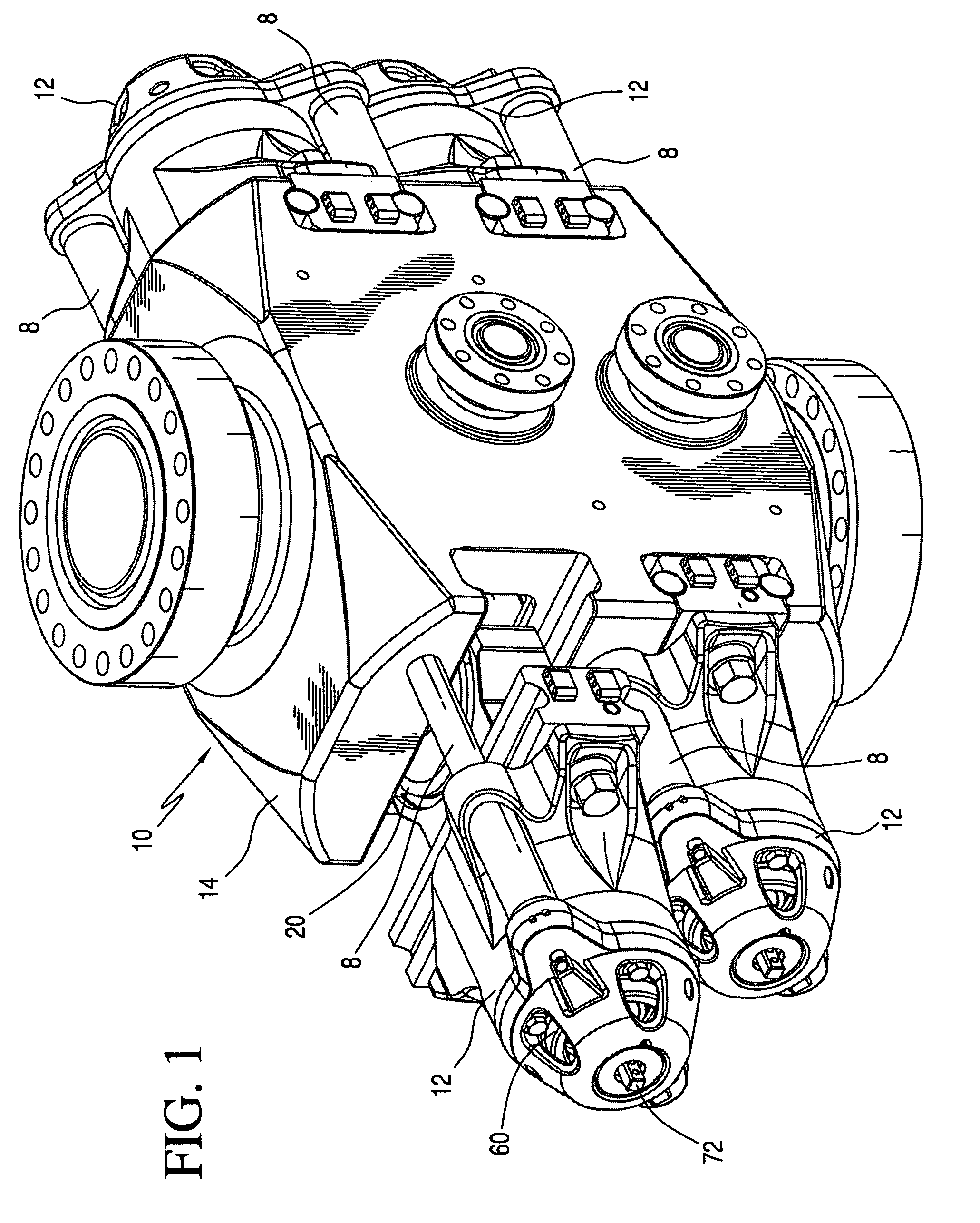
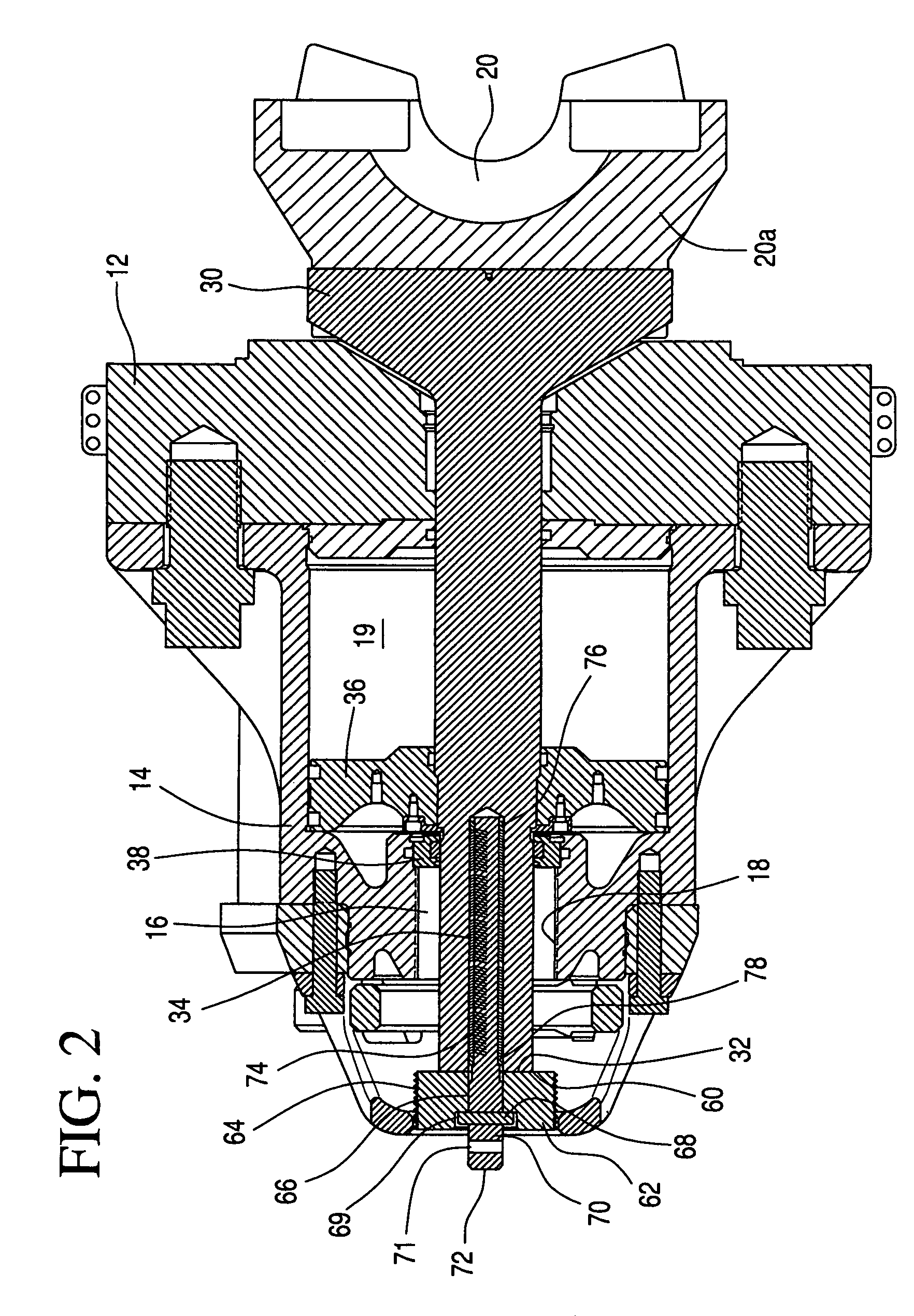
[0034]FIG. 1 shows a blowout preventer 10 according to the present invention with movable bonnets 12 each movable with respect to a main body 14. A ram 20 on a ram shaft 30 (see FIGS. 1 and 2) projects from each bonnet 12. An outer end 72 of a torquing shaft 70 of a locking assembly 60 according to the present invention is outside each bonnet 12.

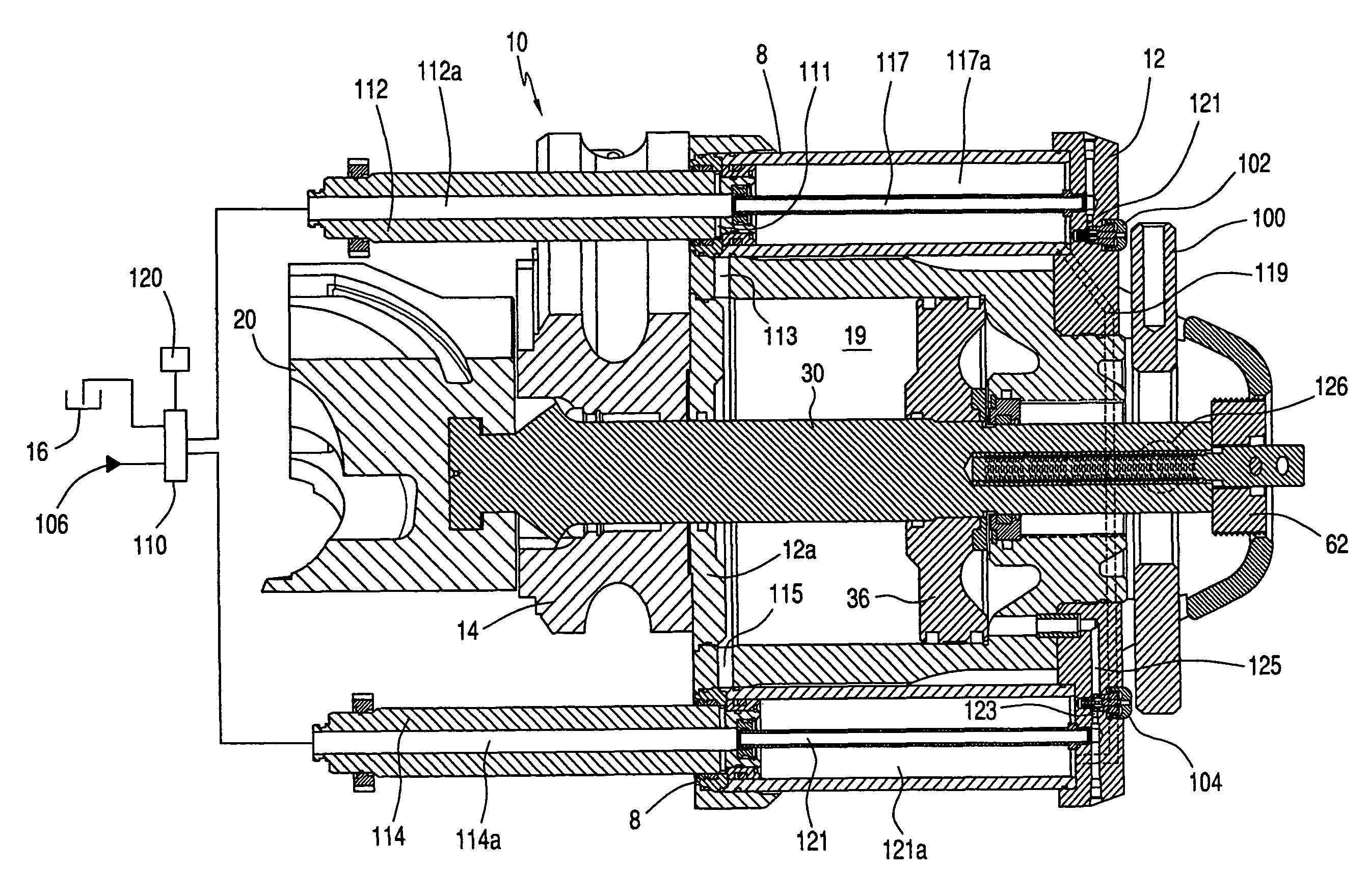
[0035]A piston 36 connected to the ram shaft 30 moves within a chamber 19 to move the ram shaft 30 so that the ram 20 can engage a tubular. Power fluid enters the chamber 19 via an inlet and exits via an outlet (see FIG. 6).

[0036]Part of the torquing shaft 70 is disposed within a channel 34 in the ram shaft 30. Springs 74 abut a stop 76 at one end of the torquing shaft 70 and a stop 78 at another location on the torquing shaft 70 to bias a locking shaft 62 inwardly and to maintain alignment of threads 64 on the exterior of the locking shaft 62 and interior threads 18 of a channel 16 in the bonnet 12. The torquing shaft 70 is secured to the l...


PUM


Abstract

A blowout preventer including, in certain aspects, a main body, a bonnet movably connected to the main body, the bonnet having a bonnet channel with interior threading, a ram shaft with a first portion extending through the main body and a second portion extending through the bonnet, the ram shaft having a ram shaft channel therein and an outer end, a ram connected to the ram shaft for selectively engaging a pipe, a locking assembly for selectively locking the ram shaft, the locking assembly including a torquing shaft with a portion within the ram shaft channel, the torquing shaft having an external end projecting beyond the bonnet, a locking shaft secured to the torquing shaft, the locking shaft having exterior threading for threadedly engaging the interior threading of the bonnet channel, and the locking shaft rotatable within the bonnet channel to abut the outer end of the ram shaft to releasably lock the ram shaft in position.

Description

BACKGROUND OF THE INVENTION[0001]1. Field of the Invention[0002]The present invention is directed to; high pressure containment apparatuses; blowout preventers; to ram locking mechanisms for them; and to methods of their use.[0003]2. Description of Related Art[0004]In a variety of situations, blowout preventers are used to control sub-surface pressures that may adversely affect equipment used in drilling oil and gas wells. Manual mechanisms and pneumatic or hydraulic pressure are employed to act on a piston to close or open ram sealing elements. Often hydraulic actuation is used since the required closing forces are relatively high. Hydraulic actuation force is applied to a cylinder containing a piston which in turn acts on a shaft having a ram element connected thereto. In certain prior art blowout preventer systems, a ram locking member is operable by turning an exterior shaft extension projecting from the blowout preventer. Alternatively the locking member is movable automaticall...

Claims


Application Information

Patent Timeline
Patent Type & Authority Patents(United States)
IPC IPC(8): E21B33/06
CPCE21B33/062
Inventor SPRINGETT, FRANK BENJAMINWEIR, JAMES WILLIAM
Owner VARCO I P INC
Why Eureka
Try Eureka